Unexplained pump failures can cause major operational downtime.
These disruptions lead to costly delays and damage your business's reputation.
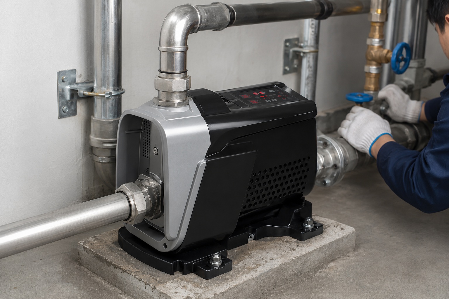
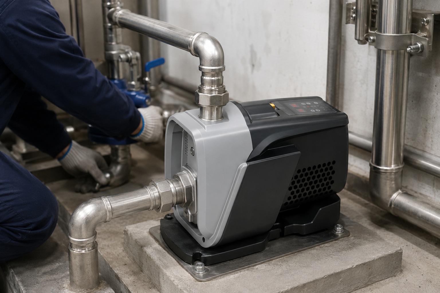
Understanding how a centrifugal pump works is the first step to preventing these issues.
A centrifugal pump operates by using a rotating impeller to accelerate a liquid. This high-speed rotation throws the liquid outward due to centrifugal force. The pump's casing, known as a volute, then slows the liquid down, converting its velocity into high-pressure energy, which drives the fluid through the system.
To truly master pump operation, you need to understand each part of the process.
This knowledge empowers you to select the right equipment and troubleshoot problems effectively.
Let's dive into the mechanics, starting with the most critical first step.
This journey will transform your understanding from basic to expert.
The Foundation of Flow: What is pump priming and why does it matter?
Starting a pump without liquid can lead to immediate and severe damage.
This mistake, known as running dry, can cause overheating and catastrophic failure.
Priming is the simple act of filling the pump with liquid before starting it.
Priming a centrifugal pump means ensuring the casing and suction line are completely full of liquid, with no air pockets. This is vital because these pumps cannot effectively compress air. Without liquid, the impeller spins uselessly, failing to create the pressure needed to draw more fluid into the pump.
The Physics Behind Priming
Priming is not just a procedural step.
It is a prerequisite rooted in the physics of fluid dynamics.
Centrifugal pumps are designed to move liquids, which are virtually incompressible.
Air, however, is a gas and is highly compressible.
When a pump is filled with air instead of liquid, the impeller's rotation does little more than slightly compress the air.
It cannot generate the significant pressure differential required to create suction.
This condition is often called "air-bound" or "air-locked."
The pump fails to draw liquid from the source, and no flow is produced.
A pump that is 97% primed might still only deliver 40% of its rated capacity.
Just a 3% air volume can slash performance by more than half.
Consequences of Improper Priming
Running a centrifugal pump without proper priming leads to a state known as 'running dry'.
This is one of the most common causes of premature pump failure.
The consequences are both immediate and severe.
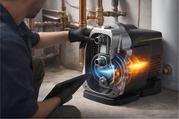
First, the mechanical seal, which prevents leaks, relies on the pumped liquid for lubrication and cooling.
Without this liquid, the seal faces rapidly generate intense frictional heat, often exceeding 200°C (392°F) within seconds.
This can cause the seal faces to warp, crack, or completely disintegrate.
Second, the impeller and casing can suffer thermal damage.
As the impeller spins at high speed (often 1500-3000 RPM), the trapped air and any small amount of liquid will heat up due to friction and compression.
This can cause plastic components to melt or metal parts to gall and seize.
Methods of Priming
There are several methods to ensure a pump is correctly primed.
The best method depends on the pump's location and application.
| Priming Method | Description | Best For |
|---|---|---|
| Manual Priming | Manually pouring liquid into the pump casing through a priming port until it is full. | Simple, small-scale applications where the pump is easily accessible. |
| Foot Valve | A type of check valve installed at the end of the suction line. It keeps the line full of liquid when the pump is off. | Suction lift applications where the liquid source is below the pump. |
| Vacuum Priming | An external vacuum pump is used to remove air from the suction line and casing, drawing liquid up into the pump. | Large-scale systems or where manual priming is impractical. |
| Self-Priming Pumps | These pumps have a special casing design with a large internal reservoir, allowing them to retain liquid and re-prime automatically. | Applications requiring frequent start-stop cycles or where air may enter the system. |
Choosing the right priming method is essential for reliable operation.
It protects the pump, ensures consistent performance, and minimizes maintenance needs.
The Heart of the Machine: How does the impeller create flow?
An inefficient pump wastes energy and drives up operational costs.
This poor performance directly impacts your bottom line and system output.
The impeller's design and rotation are key to achieving high efficiency.
The impeller is the rotating component at the heart of the pump. Driven by a motor, its spinning vanes transfer energy to the liquid. This rotation uses centrifugal force to throw the liquid from the center (the eye) to the outer edge, creating a continuous flow and initiating the pumping process.
From Rotation to Energy Transfer
The impeller's primary job is to convert mechanical energy from the motor into kinetic energy in the liquid.
As the pump's shaft rotates, the impeller spins with it.
Liquid enters the pump axially through the inlet, right into the center of the impeller, an area called the eye.
Once in the eye, the curved vanes of the spinning impeller catch the liquid.
They force the liquid to rotate along with them.
This forced rotation subjects the liquid to a powerful outward force: centrifugal force.
This is the same principle that keeps water in a bucket when you swing it in a circle.
The liquid is accelerated radially, moving from the low-pressure eye toward the high-velocity tips of the impeller vanes.
By the time the liquid leaves the impeller's outer edge, its velocity has increased dramatically.
A typical industrial pump can accelerate fluid to speeds over 30 meters per second (100 ft/s).
The Role of Impeller Design
Not all impellers are created equal.
Their design has a profound impact on the pump's performance, efficiency, and suitability for different applications.
There are three main types of impellers.
Open Impellers
Open impellers consist of vanes attached to a central hub, without any side walls (shrouds).
This design makes them less prone to clogging.
They are ideal for pumping liquids containing solids, like slurries or wastewater.
However, their efficiency is generally lower, often around 50-65%, due to higher "slip" (liquid recirculating between the vanes and casing).
Semi-Open Impellers
Semi-open impellers have a back wall (shroud) that adds mechanical strength.
The vanes are open on the other side.
They offer a balance between the clog-resistance of open impellers and the efficiency of closed ones.
Their typical efficiency ranges from 60% to 75%.
They are commonly used for liquids with some suspended solids.
Closed Impellers
Closed impellers have vanes enclosed between two shrouds (a front and back wall).
This design is the most efficient, often reaching efficiencies of 80-90% or more.
The shrouds guide the fluid flow precisely, minimizing recirculation and maximizing energy transfer.
However, their narrow passages make them suitable only for clear, low-viscosity liquids, as they can easily clog with solids.
| Impeller Type | Key Feature | Best For | Typical Efficiency |
|---|---|---|---|
| Open | Vanes on a hub, no shrouds | Liquids with high solids content (e.g., slurries) | 50% - 65% |
| Semi-Open | Vanes with a back shroud | Liquids with moderate solids content (e.g., wastewater) | 60% - 75% |
| Closed | Vanes between two shrouds | Clear, clean liquids | 80% - 90%+ |
The choice of impeller is a critical engineering decision.
It directly influences the pump's ability to handle specific fluids while optimizing energy consumption.
Understanding these differences helps you specify the right pump for your customer's needs.
From Speed to Strength: How is pressure generated in a pump?
High-velocity flow is useless without sufficient pressure to move it.
A pump that only creates speed cannot overcome system resistance like pipes and valves.
The pump's casing is ingeniously designed to convert this speed into pressure.
Pressure is generated in the volute, the spiral-shaped casing surrounding the impeller. As the high-velocity liquid exits the impeller, it enters the volute's progressively larger channel. This expansion slows the liquid down, converting its kinetic energy (velocity) into potential energy (pressure), as described by Bernoulli's Principle.
The Magic of the Volute Casing
The volute is the stationary, snail-shaped chamber that collects the liquid discharged by the impeller.
Its design is one of the most clever aspects of a centrifugal pump.
The volute's cross-sectional area gradually increases from its starting point (the "cutwater" or "tongue") to the final discharge nozzle.
Liquid leaves the impeller's edge at its maximum velocity.
As this fast-moving liquid enters the expanding volute, it has more room to spread out.
This expansion forces the liquid to decelerate.
According to a fundamental law of fluid dynamics, Bernoulli's Principle, energy in a fluid system must be conserved.
When the kinetic energy component (velocity) decreases, the potential energy component (pressure) must increase to maintain this balance.
The volute effectively acts as a diffuser.
It trades the "useless" high velocity for "useful" high pressure.
This pressure is what enables the pump to push the liquid through long pipes, up to higher elevations, and through restrictive components like filters and valves.
For example, a fluid leaving the impeller at 30 m/s might slow to 5 m/s in the volute. This dramatic decrease in velocity results in a significant increase in pressure.
Balancing Act: Radial Thrust and Diffuser Vanes
An ideal volute design is not just about creating pressure.
It's also about maintaining the pump's mechanical integrity.
The pressure inside the volute is not uniform around the impeller.
When the pump operates at its Best Efficiency Point (BEP), the flow into the volute is smooth, and the pressure distribution is relatively even.
However, if the pump operates far from its BEP, the flow becomes mismatched with the volute's geometry.
This creates an uneven pressure distribution around the impeller.
This imbalance results in a net force pushing the impeller sideways, known as radial thrust.
High radial thrust can cause several problems:
- Shaft Deflection: The force can bend the pump shaft.
- Bearing Wear: It puts excessive load on the bearings, leading to premature failure.
- Seal Failure: Shaft deflection can cause the mechanical seal to leak.
- Vibration and Noise: The pump will run less smoothly, increasing wear and tear.
To counteract this, some high-pressure pumps use a different design.
Diffuser Pumps
Instead of a volute, these pumps use a set of stationary vanes, called a diffuser, that surround the impeller.
The diffuser consists of multiple passages that gradually expand.
It performs the same function as a volute—converting velocity to pressure—but in a more controlled and structurally balanced way.
| Feature | Volute Casing | Diffuser Casing |
|---|---|---|
| Design | Single spiral channel | Multiple stationary vanes |
| Pressure Conversion | Gradual expansion of the single channel | Gradual expansion through multiple passages |
| Radial Balance | Susceptible to radial thrust when off-BEP | Inherently better balanced due to symmetry |
| Application | Most general-purpose pumps | High-pressure, multi-stage pumps |
| Cost & Complexity | Simpler, lower cost | More complex and expensive to manufacture |
Understanding the role of the volute and diffuser is key to selecting a pump that will not only perform well but also last.
It highlights the importance of operating a pump near its designed BEP for maximum efficiency and longevity.
The Science of Suction: How does a pump pull liquid in?
A pump that can't pull liquid from its source is completely ineffective.
If the suction process fails, the entire system grinds to a halt.
The creation of a low-pressure zone is the secret to a pump's pulling power.
As the impeller throws liquid outwards, it leaves behind a region of low pressure at its center, the pump eye. The higher atmospheric pressure (or system pressure) on the surface of the source liquid then pushes the liquid up the suction pipe and into the pump to fill this void.
Understanding NPSH: The Key to Suction Performance
The pump itself does not "suck" in the conventional sense.
It is more accurate to say that the pump allows liquid to be pushed into it.
This process is governed by a critical parameter: Net Positive Suction Head (NPSH).
NPSH is a measure of the total pressure at the pump's suction inlet.
It has two essential components.
NPSHA: Net Positive Suction Head Available
NPSHA is a characteristic of your system.
It is the absolute pressure that is available at the pump's suction port.
It is calculated based on several factors:
- Source Pressure (H_p): The absolute pressure on the liquid's surface in the source tank. This is often atmospheric pressure but can be higher or lower in a closed system.
- Static Head (H_s): The vertical distance between the liquid surface and the pump's centerline. It is positive if the pump is below the liquid (flooded suction) and negative if the pump is above it (suction lift).
- Friction Loss (H_f): The pressure lost due to friction as the liquid flows through the suction piping, valves, and fittings.
- Vapor Pressure (H_vp): The pressure at which the liquid will start to boil at its current temperature. This pressure must be overcome.
The formula is: NPSHA = H_p ± H_s - H_f - H_vp
NPSHR: Net Positive Suction Head Required
NPSHR is a characteristic of the pump itself.
It is the minimum pressure required at the pump inlet to prevent the liquid from boiling inside the pump.
This value is determined by the pump manufacturer through testing and varies with the pump's flow rate.
It is usually shown on the pump's performance curve.
The Danger of Cavitation
For successful operation, there is one non-negotiable rule: NPSHA must always be greater than NPSHR.
A safety margin of at least 1-2 meters (3-6 feet) is highly recommended.
If NPSHA drops to or below NPSHR, a destructive phenomenon called cavitation will occur.
Here's what happens:
- Bubble Formation: The pressure inside the pump eye drops below the liquid's vapor pressure. The liquid begins to boil at its ambient temperature, forming small vapor bubbles.
- Bubble Transport: These bubbles are carried by the flow from the low-pressure eye toward the high-pressure areas at the impeller's edge.
- Bubble Implosion: As the bubbles enter the high-pressure region, the surrounding pressure instantly crushes them. This collapse is violent, creating a powerful micro-jet of liquid.
This implosion generates intense shockwaves, localized temperatures up to 10,000°C, and pressures exceeding 700 bar (10,000 psi).
| Consequence of Cavitation | Description |
|---|---|
| Physical Damage | The micro-jets act like tiny hammers, physically chipping away at the impeller and casing material. This creates a distinct pitting and erosion pattern. |
| Noise and Vibration | The continuous bubble implosion sounds like gravel or marbles are passing through the pump. This causes significant vibration, damaging bearings and seals. |
| Performance Loss | The vapor-filled pump cannot move liquid effectively, leading to a sharp drop in flow rate and pressure. Efficiency plummets. |
Preventing cavitation is paramount.
It involves careful system design to maximize NPSHA (e.g., larger, shorter suction pipes) and selecting a pump with a low NPSHR for the required duty point.
Ensuring Non-Stop Performance: What maintains continuous flow?
An intermittent or pulsing flow can disrupt industrial processes.
Inconsistent output from a pump reduces system reliability and efficiency.
A positive feedback loop is what ensures a steady, uninterrupted stream.
Continuous flow is maintained by a self-sustaining cycle. As high-pressure liquid is discharged, the low-pressure zone at the impeller eye is constantly refilled by the source liquid. This cycle repeats as long as the impeller is spinning and there is liquid available at the suction side.
The Unbroken Chain of Pumping
The operation of a centrifugal pump is a perfect example of a continuous process.
It is not a series of distinct start-and-stop actions.
Instead, every stage happens simultaneously and relies on the others.
Think of it as an unbroken chain of events.
- Discharge Creates a Void: The discharge of pressurized liquid from the volute actively empties the pump casing.
- Impeller Fills the Void from the Center: The impeller is constantly flinging liquid towards the volute, creating a continuous demand for more liquid at its center.
- Vacuum at the Eye Pulls in More Liquid: This demand creates a persistent low-pressure zone at the impeller eye.
- Source Pressure Feeds the Suction Line: Higher external pressure on the source liquid continuously pushes it into the suction line to fill that low-pressure zone.
This cycle is seamless and instantaneous.
The moment a molecule of liquid is discharged, another molecule is already entering the pump's suction inlet.
This is why the process is called "pumping," even though it relies on pressure differentials rather than direct displacement like a piston pump.
The flow rate is directly tied to the speed of the impeller.
Doubling the impeller speed (RPM) will roughly double the flow rate, according to the Pump Affinity Laws.
Factors Affecting Flow Stability
While the principle is continuous, several factors in a real-world system can disrupt this steady flow.
Maintaining stable operation requires managing these variables.
System Resistance
The most significant factor is the system's resistance, also known as the total dynamic head (TDH).
This is the total pressure the pump must overcome.
It includes:
- Static Head: The vertical height the liquid must be lifted.
- Friction Head: Pressure losses from pipes, elbows, valves, and other fittings.
- Pressure Head: Any pressure in the destination tank that the pump must work against.
A pump will always operate at the intersection of its performance curve and the system's resistance curve.
If the system resistance increases (e.g., a valve is partially closed), the flow rate will decrease.
If resistance decreases, the flow rate will increase.
Suction Conditions
As discussed, stable suction is critical.
Any air entering the suction line can interrupt the flow.
Even small air leaks can cause the pump to lose prime or operate erratically.
Variations in the source liquid level will also change the NPSHA, potentially affecting suction stability.
A well-designed system will have a vortex breaker at the suction inlet to prevent air from being drawn in when the liquid level is low.
The Role of VFDs in Modern Pumping
In the past, managing flow was often done by throttling a discharge valve.
This is highly inefficient because the pump still runs at full speed, but its output is artificially restricted.
The excess energy is wasted as heat and noise.
Today, the superior method is to use a Variable Frequency Drive (VFD).
A VFD controls the speed of the pump's motor directly.
By adjusting the motor's speed, you can precisely control the pump's output to match the system's demand.
| Feature | Throttling Control | VFD Control |
|---|---|---|
| Method | Partially closes a valve to increase system resistance. | Reduces motor RPM to shift the pump curve down. |
| Energy Efficiency | Very low. Wastes significant energy. | Very high. Energy savings can be 50% or more. |
| Pump Wear | Increases pressure and thrust, leading to higher wear. | Reduces pump speed, extending the life of bearings and seals. |
| Process Control | Less precise, can cause pressure spikes. | Highly precise and smooth control. |
| Initial Cost | Low (cost of a valve). | Higher (cost of a VFD). |
| Lifecycle Cost | High, due to wasted energy and maintenance. | Low, due to energy savings and reduced maintenance. |
Using a VFD maintains a stable, continuous flow perfectly matched to the application's needs.
It is the cornerstone of modern, efficient, and reliable pump system design.
Conclusion
Understanding a centrifugal pump's operation is simple.
It uses an impeller to create flow and a volute to build pressure.
This knowledge is key to reliable and efficient fluid handling.
FAQs
What are the two main parts of a centrifugal pump?
The two main parts are the impeller, which is the rotating component that moves the liquid, and the volute casing, the stationary part that converts velocity to pressure.
What is the difference between a centrifugal pump and a positive displacement pump?
A centrifugal pump uses an impeller to generate a variable flow based on system pressure. A positive displacement pump traps and moves a fixed volume of fluid, delivering a constant flow regardless of pressure.
What causes a centrifugal pump to lose prime?
A pump can lose prime due to air leaks in the suction line, a faulty foot valve, or if the liquid level in the source tank drops below the suction inlet.
Why is my centrifugal pump not building pressure?
This can be caused by running the pump in the wrong direction, having air in the system (loss of prime), a clog in the impeller, or excessive wear increasing internal clearances.
Can a centrifugal pump run backwards?
Yes, but it will be highly inefficient, producing much lower flow and pressure. Running it backward for extended periods can also cause the impeller to unscrew from the shaft.
How do you control the flow of a centrifugal pump?
The most efficient way is with a Variable Frequency Drive (VFD) to adjust motor speed. A less efficient method is throttling a valve on the discharge side of the pump.
What is a pump curve?
A pump curve is a graph provided by the manufacturer. It shows the pump's performance, detailing the relationship between flow rate, head (pressure), efficiency, power required, and NPSHR.
What is pump cavitation and how can it be avoided?
Cavitation is the formation and collapse of vapor bubbles inside the pump, which causes damage. It is avoided by ensuring the Net Positive Suction Head Available (NPSHA) in your system is always greater than the NPSH Required (NPSHR) by the pump.