Struggling with insufficient fluid pressure in your system?
This common problem can halt operations and impact efficiency.
A centrifugal pump is the engineered solution to overcome this challenge effectively.
Yes, the primary function of a centrifugal pump is to increase the pressure of a fluid.
It achieves this by converting rotational energy from a motor into kinetic energy within the fluid.
This kinetic energy is then transformed into potential energy, which manifests as a significant pressure increase.
Understanding this core function is just the beginning.
How this pressure is generated, controlled, and applied is what truly sets these pumps apart as industrial workhorses.
The principles behind this process are rooted in fundamental physics, but their application is a feat of modern engineering.
Let's explore the mechanics that allow a simple rotating component to move massive volumes of fluid and build substantial pressure, making it indispensable across countless industries.
How Does a Centrifugal Pump Generate Pressure?
Are you trying to understand the exact mechanism behind pressure generation?
It can seem complex.
Failing to grasp this concept can make pump selection and troubleshooting difficult.
A centrifugal pump generates pressure through a two-step energy conversion process.
First, the rotating impeller imparts velocity to the fluid, increasing its kinetic energy.
Second, the volute casing diffuses the flow, converting this high velocity into high static pressure as the fluid exits the pump.
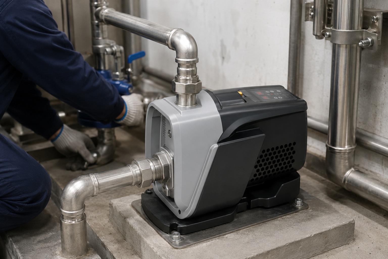
The journey of a fluid particle through a centrifugal pump is a rapid and precisely engineered transformation.
It all begins at the suction nozzle, or the eye of the impeller.
Here, the fluid enters the pump at a relatively low pressure.
As the motor spins the pump shaft, the attached impeller rotates at high speed, often thousands of revolutions per minute (RPM).
The fluid is drawn into the rotating vanes of the impeller.
The Role of the Impeller
The impeller's design is critical.
Its curved vanes catch the incoming fluid and sling it outwards using centrifugal force.
This is the first and most crucial energy transfer.
The motor's mechanical energy becomes the fluid's kinetic energy (energy of motion).
The velocity of the fluid can increase by over 90% in this stage alone.
Think of it like spinning a bucket of water; the water is forced against the outer wall.
In the pump, this outward force dramatically accelerates the fluid.
The Function of the Volute Casing
Once the high-velocity fluid leaves the impeller's outer edge, it enters the volute.
The volute is a spiral-shaped casing with a cross-sectional area that gradually increases towards the discharge nozzle.
This carefully designed shape is a diffuser.
Its purpose is to slow the fluid down in a controlled manner.
According to Bernoulli's principle, as the fluid's velocity decreases, its pressure must increase.
This conversion of kinetic energy into potential energy (pressure) is the second key step.
The volute efficiently manages this conversion, minimizing energy loss from turbulence.
By the time the fluid reaches the discharge port, its velocity is lower, but its pressure is substantially higher than when it entered.
A well-designed pump can convert up to 85% of the kinetic energy into pressure.
| Pump Component | Primary Function | Energy Conversion Stage |
|---|---|---|
| Impeller | Accelerates fluid outwards | Mechanical Energy → Kinetic Energy |
| Volute Casing | Slows fluid down | Kinetic Energy → Potential Energy (Pressure) |
| Suction Nozzle | Guides fluid to impeller eye | Fluid Inlet |
| Discharge Nozzle | Directs pressurized fluid out | Fluid Outlet |
This elegant, two-stage process allows centrifugal pumps to be both simple in mechanical design and highly effective at generating the pressure required for countless applications, from municipal water supply to chemical processing.
The final discharge pressure is a direct result of the impeller's rotational speed and diameter, as well as the hydraulic design of the casing.
What Factors Affect the Pressure a Centrifugal Pump Can Produce?
Need to achieve a specific pressure but your pump isn't delivering?
Uncontrolled variables can lead to system underperformance and costly downtime.
Knowing the key factors allows precise control over pump output.
The pressure, or head, produced by a centrifugal pump is primarily determined by the impeller's rotational speed and its diameter.
System characteristics, such as fluid viscosity and the total static head, also play a crucial role in the final discharge pressure delivered to the system.
The pressure a centrifugal pump generates is not a fixed value.
It is a dynamic output that depends on a combination of pump design characteristics and system conditions.
Misunderstanding these variables can lead to inefficient operation or even pump failure.
A professional approach requires a deep dive into the elements that dictate the final pressure output, often visualized through a pump performance curve.
This curve charts the relationship between flow rate (Q) and head (H), which is a measure of pressure.
Pump-Specific Factors
These are variables related to the physical design and operation of the pump itself.
They are the primary drivers of the pump's potential pressure output.
-
Impeller Speed (RPM): This is one of the most influential factors. According to the Affinity Laws for pumps, the pressure (head) generated is proportional to the square of the speed change. Doubling the pump's speed theoretically quadruples the pressure it can produce. This is why Variable Speed Drives (VSDs) are so effective for controlling pump output, allowing operators to fine-tune pressure by adjusting motor speed with up to 95% efficiency.
-
Impeller Diameter: A larger impeller diameter means the fluid is thrown outwards at a higher tangential velocity for the same RPM. This results in a greater increase in kinetic energy and, consequently, a higher potential pressure. The pressure generated is proportional to the square of the impeller's diameter. Even a small increase of 10% in diameter can lead to a 21% increase in potential head.
-
Number and Design of Vanes: The geometry of the impeller vanes—their curvature, number, and angle—influences the efficiency of energy transfer. More vanes can provide a smoother flow, but too many can restrict the passage. The design is a careful balance optimized for specific fluid types and applications.
System-Dependent Factors
These factors relate to the environment and the fluid the pump is working with.
They often create resistance that the pump's generated pressure must overcome.
-
Fluid Density and Viscosity: Pump performance curves are typically based on clear water. A denser fluid requires more power to accelerate, and the pressure generated (in terms of psi or bar) will be higher for the same head. Conversely, higher viscosity fluids increase frictional losses within the pump and piping, which can significantly reduce the effective pressure and flow rate. For fluids with a viscosity over 10% higher than water, performance corrections are necessary.
-
Total Head of the System: The pump doesn't just generate pressure; it has to work against the existing system head. This is comprised of:
- Static Head: The vertical height difference between the source fluid level and the destination. This is a constant pressure the pump must always overcome.
- Friction Head: The pressure lost due to friction as the fluid moves through pipes, valves, and fittings. This loss increases with the square of the flow rate.
The final operating point of the pump is where the pump's performance curve intersects with the system's resistance curve.
Therefore, changing any of these factors, like closing a valve (increasing friction head), will shift the operating point and change the discharge pressure.
How Do Flow Rate and Pressure Interact in a Centrifugal Pump?
Are you confused by the relationship between flow and pressure?
Assuming one can be changed without affecting the other leads to major operational errors.
Understanding their inverse relationship is key to system design.
In a centrifugal pump, flow rate and pressure (head) are inversely related.
As the flow rate increases, the discharge pressure decreases.
Conversely, as the flow rate decreases (for example, by closing a discharge valve), the pressure generated by the pump increases, up to its shut-off head.
The inverse relationship between flow and pressure is one of the most fundamental concepts in centrifugal pump operation.
It is graphically represented by the pump's main performance curve.
This curve is not just a theoretical diagram; it is the operational fingerprint of a specific pump model, determined through rigorous factory testing.
Every point on this curve represents a possible operating condition for the pump.
You cannot independently select a flow rate and a pressure; they are intrinsically linked.
Understanding the Pump Performance Curve
A standard pump curve plots the Head (pressure) on the vertical y-axis against the Flow Rate on the horizontal x-axis.
-
Shut-off Head: This is the point on the far left of the curve where the flow rate is zero (Q=0). It represents the maximum pressure the pump can generate. This condition occurs when the discharge valve is completely closed. While the pressure is at its peak, the pump is doing no useful work, and running it in this state for extended periods can cause overheating and damage. The shut-off head is typically 110% to 130% of the head at the Best Efficiency Point.
-
Best Efficiency Point (BEP): This is the point on the curve where the pump operates most efficiently, converting the highest percentage of motor energy into fluid energy. Designing a system to operate at or near the BEP ensures lower energy consumption, reduced vibration, and a longer operational lifespan for the pump. Operating more than 25% away from the BEP can significantly increase maintenance costs.
-
Run-out Point: This is the maximum flow rate on the far right of the curve. At this point, the pump's discharge pressure is at its minimum. Operating a pump at run-out can lead to cavitation, where low pressure causes vapor bubbles to form and collapse, which can severely damage the impeller and casing.
Practical Implications of the Relationship
This inverse relationship has direct consequences for system design and operation.
-
Throttling a Valve: When you partially close a valve on the discharge side of the pump, you are increasing the system's resistance (friction head). This forces the pump's operating point to move to the left along its curve, resulting in a lower flow rate and a higher discharge pressure.
-
Opening a Valve: Conversely, opening a valve or adding a parallel discharge line reduces system resistance. The operating point shifts to the right along the curve, leading to a higher flow rate but a lower discharge pressure.
-
System Sizing: Engineers use the system resistance curve and the pump performance curve to select the right pump. The goal is to ensure that the intersection of these two curves (the operating point) falls at or very near the pump's BEP for the desired flow rate and pressure. A mismatch can result in a pump that is either oversized, wasting energy, or undersized, failing to meet system demands.
| Operating Condition | Flow Rate (Q) | Pressure (H) | Notes |
|---|---|---|---|
| Shut-off | Zero | Maximum | High risk of overheating; no useful work done. |
| Near BEP | Optimal | Optimal | Most efficient, reliable, and cost-effective operation. |
| Run-out | Maximum | Minimum | High risk of cavitation and motor overload. |
Mastering this relationship is non-negotiable for anyone responsible for designing, operating, or maintaining a fluid transfer system powered by centrifugal pumps.
It is the key to achieving efficiency, reliability, and control.
Can Centrifugal Pumps Handle Both High Pressure and High Flow?
Do you need a single pump for a high-pressure, high-flow application?
It's a common requirement, but it can be a significant engineering challenge.
Choosing the wrong pump type can lead to inefficiency and failure.
While a single-stage centrifugal pump has limitations, specialized designs can handle both high pressure and high flow.
Multi-stage pumps are used for very high pressures, while double-suction or parallel pump configurations are used for very high flow rates. Achieving both often requires careful selection.
The ability of a centrifugal pump to deliver high pressure and high flow simultaneously is constrained by its design and the laws of physics.
As we've seen, for any single pump, increasing flow inherently decreases pressure.
However, the pump industry has developed several clever solutions to meet the demands of applications requiring both high performance metrics, such as boiler feedwater systems, large-scale irrigation, or municipal water distribution networks.
The solution depends on which parameter—pressure or flow—is the more challenging requirement.
Achieving High Pressure: Multi-stage Pumps
When an application demands pressures that a single impeller cannot generate, the solution is the multi-stage centrifugal pump.
-
How They Work: A multi-stage pump contains multiple impellers housed in a single casing. The fluid is discharged from the first impeller and immediately guided into the suction eye of the second impeller. This process is repeated through each stage. Each impeller, or stage, adds an increment of pressure to the fluid.
-
Pressure Calculation: The total pressure generated by the pump is approximately the pressure from a single stage multiplied by the number of stages. A 4-stage pump, for example, can produce roughly four times the pressure of a comparable single-stage pump at the same flow rate. Some high-pressure pumps used in industries like reverse osmosis can have 50 or more stages, generating pressures well over 1,000 psi (70 bar).
Achieving High Flow: Double-Suction and Parallel Pumps
When the primary challenge is moving a massive volume of fluid, the focus shifts from adding pressure in series to increasing the flow capacity.
-
Double-Suction Pumps: This design features an impeller that accepts fluid intake from both sides. This effectively splits the flow into two halves, with each half entering one side of the impeller. By doing this, the inlet fluid velocity is reduced, which significantly lowers the Net Positive Suction Head required (NPSHr) and reduces the risk of cavitation at high flow rates. It nearly doubles the flow capacity compared to a single-suction pump of the same impeller diameter.
-
Pumps in Parallel: Another common strategy is to install two or more pumps in a parallel configuration. Their discharges are combined into a single header. When two identical pumps run in parallel, the total flow rate at a given head is effectively doubled. This provides both high capacity and redundancy. If one pump fails or requires maintenance, the other can often continue to supply a reduced flow, preventing a complete system shutdown. Over 70% of critical cooling water systems use parallel pump configurations for this reason.
The Trade-off
While these solutions are effective, there is often a trade-off.
A pump designed for extremely high pressure (like a multi-stage pump) might not have the massive flow capacity of a large, single-stage double-suction pump.
Selecting the right pump involves finding the optimal balance for a specific application's duty point on the pressure-flow map.
It often requires a detailed analysis of the system's requirements and a consultation with pump engineering specialists to identify a solution that is both effective and energy-efficient.
Conclusion
Centrifugal pumps do increase pressure.
They are fundamental machines that achieve this through a precise conversion of velocity to pressure, governed by impeller speed, diameter, and system conditions.
Frequently Asked Questions (FAQs)
1. What is the difference between pressure and head in a pump?
Head is the height a pump can lift a fluid, measured in feet or meters. Pressure is the force per unit area, measured in psi or bar. Head is independent of a fluid's density.
2. Can a centrifugal pump run dry?
No, a centrifugal pump should not run dry. The pumped fluid is required for cooling and lubrication. Running dry can quickly cause the mechanical seal to overheat and fail.
3. What is pump cavitation and how do you stop it?
Cavitation is the formation and collapse of vapor bubbles inside a pump due to low pressure. It can be stopped by increasing suction pressure or decreasing fluid temperature and friction losses.
4. How do you increase the pressure of a centrifugal pump?
You can increase the pressure by increasing the pump's rotational speed with a VSD, installing a larger diameter impeller, or using a multi-stage pump for significantly higher pressure needs.
5. What happens if you run a centrifugal pump with the discharge valve closed?
Running with the discharge valve closed (shut-off head) causes the fluid inside to heat up rapidly. This can lead to overheating, seal failure, and potentially catastrophic pump damage.
6. Do you need a check valve on a centrifugal pump?
Yes, a check valve is typically installed on the discharge side. It prevents backflow when the pump stops, which protects the pump from reverse rotation and water hammer.
7. How efficient is a centrifugal pump?
The efficiency of a centrifugal pump varies with its design and operating point. Most operate between 60% and 85% efficiency at their Best Efficiency Point (BEP), with some specialized models exceeding 90%.
8. What is the difference between a positive displacement pump and a centrifugal pump?
A centrifugal pump generates pressure by imparting velocity to a fluid, with flow varying with pressure. A positive displacement pump moves a fixed volume of fluid, delivering a constant flow regardless of pressure.