Confused by technical terms?
You hear "inverter" and "VFD" used for pumps, but you are not sure if they mean the same thing.
This confusion can lead to costly purchasing mistakes.
Yes, a Variable Frequency Drive (VFD) is a specific, advanced type of inverter.
While any inverter converts DC to AC power, a VFD adds a layer of intelligent control.
It precisely adjusts the frequency and voltage supplied to an AC motor to manage its speed and torque.

In the world of industrial equipment, especially for motors and pumps, understanding the technology behind the labels is critical for making informed decisions.
While the terms "inverter," "VFD," and "AC drive" are often used interchangeably, there are important distinctions that impact performance, efficiency, and equipment longevity.
Think of it like this: all squares are rectangles, but not all rectangles are squares.
Similarly, all VFDs contain an inverter, but not every inverter has the sophisticated control capabilities of a VFD.
This article will break down the core functions of each, explore how they differ, and dive deep into the advanced features that make VFD technology the superior choice for modern motor control applications, such as high-efficiency water booster pumps.
We will examine the technology that drives performance, the materials that ensure durability, and the intelligent systems that protect your investment.
The Core Function: What is an Inverter?
Are you unsure about the basic role of an inverter?
This simple device performs a critical task.
It is the foundation for many modern electronics, but its function is very specific.
An inverter is an electronic device with one primary job.
It converts direct current (DC) power to alternating current (AC) power.
This allows DC sources, like batteries or solar panels, to power standard AC appliances and motors.
Its function is purely electrical conversion.
The concept of an inverter is fundamental to modern power electronics.
At its heart, the device solves a basic compatibility problem between power sources and power loads.
Many energy sources, particularly renewable ones like solar panels and stored energy in batteries, produce DC power.
However, the vast majority of our electrical grid and the equipment connected to it, from household appliances to industrial motors, operate on AC power.
An inverter bridges this gap.
The Conversion Process Explained
The process of converting DC to AC is not magic; it involves high-speed electronic switches.
- Input Stage: The inverter takes a stable DC voltage as its input.
- Switching Stage: Inside the inverter, powerful transistors (like IGBTs or MOSFETs) switch on and off thousands of times per second. This rapid switching effectively "chops up" the steady DC voltage.
- Output Stage: The chopped DC voltage is then shaped and filtered. The goal is to create a smooth, repeating waveform that mimics the sine wave of standard AC grid power.
The quality of this output AC waveform is a key differentiator between types of inverters.
| Inverter Type | Output Waveform | Best Use Case |
|---|---|---|
| Square Wave | A very basic, blocky waveform. | Simple tools with universal motors. Not suitable for sensitive electronics. |
| Modified Sine Wave | A stepped, stepped approximation of a sine wave. | More compatible than a square wave, but can still cause issues with certain devices. |
| Pure Sine Wave | A smooth, clean waveform virtually identical to grid power. | The highest quality. Essential for sensitive electronics, medical equipment, and high-performance motors. |
For any application involving a motor, a pure sine wave output is crucial.
Using a lower-quality waveform can lead to operational problems.
The motor may run hotter than usual, produce excess noise, and operate less efficiently.
Over time, this can cause premature wear and even lead to complete failure of the motor windings.
Therefore, while a basic inverter can technically run a motor, it lacks the finesse required for optimal performance and control.
It acts as a simple on/off switch with a fixed voltage and frequency output, offering no ability to manage the motor's operational characteristics.
The Advanced Controller: What is a VFD?
Is a standard inverter not enough for your motor application?
You need control over speed and torque.
Simply turning a motor on and off is inefficient and causes mechanical stress.
A Variable Frequency Drive (VFD) is an intelligent motor controller.
It uses an inverter as its core component but adds a sophisticated control system.
This system allows the VFD to vary the frequency and voltage of the AC power it sends to a motor, providing precise control over its speed.
A VFD takes the fundamental principle of a pure sine wave inverter and elevates it into a comprehensive motor control system.
It is not just about converting power; it is about manipulating that power with precision to make a motor do exactly what you want it to do.
This capability transforms how we operate machinery, leading to massive gains in efficiency, control, and equipment lifespan.
The key difference lies in its architecture, which is more complex than a standard inverter.
The Three Stages of a VFD
A VFD operates in three distinct stages to achieve its goal.
- Converter (Rectifier): The first stage takes the incoming AC power from the grid and converts it into DC power. This is the opposite function of an inverter. This stage creates a stable pool of DC voltage stored in capacitors, known as the DC bus.
- DC Bus (Capacitors): This section smooths out the rectified DC power. The capacitors act like a reservoir, ensuring the next stage has a clean, stable DC voltage to work with.
- Inverter: This is the final and most critical stage. The inverter section takes the smooth DC voltage from the bus and, using a technique called Pulse Width Modulation (PWM), creates a new, variable AC output. By changing the speed and pattern of the switching transistors, the VFD can construct an AC sine wave of almost any frequency and voltage.
This ability to change the output frequency is directly linked to the motor's speed.
The fundamental relationship is defined by a simple formula:
Motor Speed (RPM) = (Frequency in Hz x 120) / Number of Motor Poles
By precisely controlling the frequency, a VFD can control the motor's RPM with incredible accuracy.
This unlocks a huge range of benefits.
Core Benefits of VFD Control
- Energy Savings: A motor running at 80% speed can use up to 50% less energy than one running at full speed. VFDs match motor output to the actual load, eliminating wasted energy.
- Soft Start/Stop: A VFD can gradually ramp up the motor's speed. This "soft start" avoids the massive inrush of electrical current and the sudden mechanical shock of starting a motor at full voltage. This drastically reduces wear on belts, gears, and couplings.
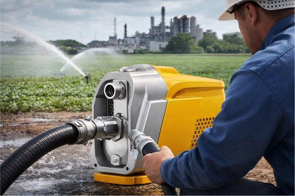
- Process Control: In applications like pumps and fans, a VFD can maintain constant pressure or flow by adjusting motor speed in real-time, improving product quality and system stability.
In essence, a VFD is a complete power-management solution specifically designed for AC motors, while a basic inverter is merely a power-conversion component.
Core Drive Technology and Performance in Modern Pumps
Are you looking for a water pump that just works?
Many pumps are noisy, inefficient, and provide fluctuating pressure.
This leads to a frustrating user experience and high electricity bills.
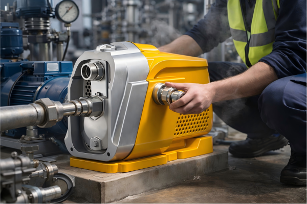
Modern booster pumps integrate VFD technology with advanced motors for superior results.
They deliver constant water pressure silently and efficiently.
This combination provides customizable pressure, quiet operation, and a soft start function that protects your entire plumbing system from mechanical shock.
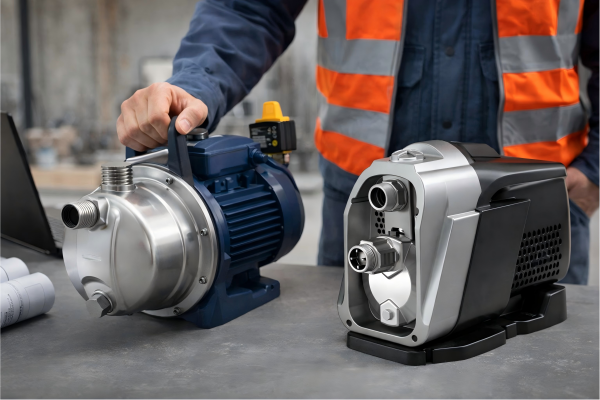
The heart of a top-tier booster pump is not just one component, but the synergy between two core technologies: a Variable Frequency Drive (VFD) and a Permanent Magnet Synchronous Motor (PMSM).
This pairing represents a significant leap forward from older, fixed-speed pump systems.
The VFD acts as the intelligent brain, while the PMSM serves as the powerful and efficient muscle.
Together, they create a system that is responsive, quiet, and exceptionally energy-efficient.
This technology moves beyond the simple on-off functionality of traditional pumps, offering a dynamic response to a building's water demands.
The VFD and PMSM Partnership
Understanding how these two components work together reveals why this technology is so effective.
-
Permanent Magnet Synchronous Motor (PMSM): Unlike traditional induction motors, a PMSM uses powerful permanent magnets embedded in its rotor. This design eliminates the need for electricity to create a magnetic field in the rotor, which significantly reduces energy losses. The result is a motor that is more efficient, runs cooler, and can achieve higher power density (more power in a smaller size).
-
Variable Frequency Drive (VFD) Controller: The VFD is perfectly matched to the PMSM. It provides the precise electrical waveforms needed to control the PMSM's speed with remarkable accuracy. The VFD constantly monitors system pressure. When a tap is opened and pressure drops, the VFD instantly increases the motor's speed. When the tap is closed and pressure rises, it slows the motor down.
This seamless integration delivers several key performance features.
Advanced Performance Features
The combination of VFD control and a PMSM enables features that were impossible with older pump designs.
| Feature | Technical Implementation | User Benefit |
|---|---|---|
| Constant Pressure | The VFD uses a pressure sensor to create a closed-loop control system, adjusting motor RPM in real-time. | A stable, shower-like experience without any annoying pressure fluctuations, even when multiple taps are used. |
| Silent Operation (≤50dB) | The PMSM's efficient design and the VFD's smooth sine wave output result in minimal electrical and mechanical noise. | The pump can be installed anywhere without causing a disturbance. It operates quieter than a normal conversation. |
| Soft Start & Soft Stop | The VFD gradually accelerates and decelerates the motor, avoiding sudden starts and stops. | This prevents "water hammer," a damaging hydraulic shockwave in pipes, and dramatically reduces mechanical stress on the pump and motor. |
| Wide Customization | The VFD's digital controls allow the user to set the target system pressure anywhere from 20% to 95% of the pump's maximum capacity. | The pump can be perfectly tailored to the specific needs of any plumbing system, from small homes to larger commercial buildings. |
These features not only provide a better user experience but also contribute directly to the system's longevity and overall efficiency.
The pump only works as hard as it needs to, saving energy and reducing wear and tear on all its components.
Excellence in Mechanical and Material Engineering
Are you worried about the longevity of your pump?
Many manufacturers use cheap components that fail prematurely.
This leads to costly repairs, downtime, and a loss of trust in the equipment.
Top-quality pumps are built with superior materials and precision engineering.
From advanced stator designs using high-grade silicon steel to premium bearings and stainless steel impellers, every component is chosen for durability, efficiency, and a long, reliable service life.
While the VFD controller and PMSM motor are the brain and muscle of a modern booster pump, the system's long-term reliability is determined by its skeleton and connective tissues—the mechanical components and the materials from which they are made.
A commitment to engineering excellence is evident in the selection of every part, no matter how small.
High-quality manufacturers understand that a pump is only as strong as its weakest link.
This philosophy drives the choice of premium materials and advanced designs for the parts that endure the most stress, heat, and hydraulic force.
The Heart of the Motor: Advanced Stator and Rotor Design
The stator and rotor are the core electromechanical parts of the motor, and their quality directly impacts efficiency and lifespan.
-
High-Grade Stator Construction: The stator is the stationary part of the motor that creates the rotating magnetic field. Superior designs focus on minimizing energy loss and managing heat effectively.
- 600-Grade Silicon Steel: This specialized steel has low hysteresis and eddy current losses, meaning less electrical energy is wasted as heat. This directly improves motor efficiency.
- Low Temperature Rise (≤50K): A low temperature rise indicates that the motor is running efficiently and that heat is being dissipated effectively. Heat is the primary enemy of motor longevity, so keeping the motor cool is paramount.
- Class F Insulation Wire: The copper windings are coated with Class F insulation, which can safely withstand high operating temperatures, providing a crucial safety margin and ensuring reliability under heavy loads.
-
High-Performance Ferrite Magnet Rotor: The rotor is the rotating part of the motor.
- Advanced Ferrite Magnet: A high-performance magnet is used that resists demagnetization even at temperatures up to 150°C. This ensures the motor maintains its power and efficiency throughout its life.
- Optional EMC+PFC: For demanding applications and markets with strict regulations, an optional configuration for Electromagnetic Compatibility (EMC) and Power Factor Correction (PFC) is available. This ensures the pump does not interfere with other electronics and uses power from the grid efficiently.
Precision in Motion: Bearings and Hydraulics
The components that handle movement and water flow are just as critical.
| Component | Material/Specification | Advantage |
|---|---|---|
| Bearings | Premium brands (e.g., NSK/C&U) | These high-precision bearings operate with less friction, resulting in 40% quieter operation and an 11% longer lifespan compared to standard bearings. |
| Impeller | AISI304 Stainless Steel | This is the component that actually moves the water. Using AISI304 stainless steel ensures excellent resistance to corrosion and abrasion, even with aggressive water quality. |
| Pump Housing | UV-Resistant ABS | The external casing protects the internal components. Using UV-resistant material prevents it from becoming brittle or discolored when exposed to sunlight in outdoor installations. |
By investing in these premium materials and engineering designs, a manufacturer builds a pump that is not just powerful and intelligent, but also fundamentally tough and durable, ready to provide years of trouble-free service.
Uncompromising Electronic Reliability and Protection
Is your equipment failing due to environmental factors?
Moisture, dust, and vibration can destroy sensitive electronics, causing unexpected shutdowns and expensive replacements for your pump's controller.
The best solution is complete electronic isolation.
By fully sealing the main controller board (PCB) in a waterproof, dustproof potting compound, all sensitive components are protected from the environment.
This simple but effective strategy can extend the controller's lifespan by years.
The controller is the most sophisticated and sensitive part of a VFD pump.
It houses the microprocessor, power transistors, and a host of delicate circuits that are responsible for monitoring, control, and protection.
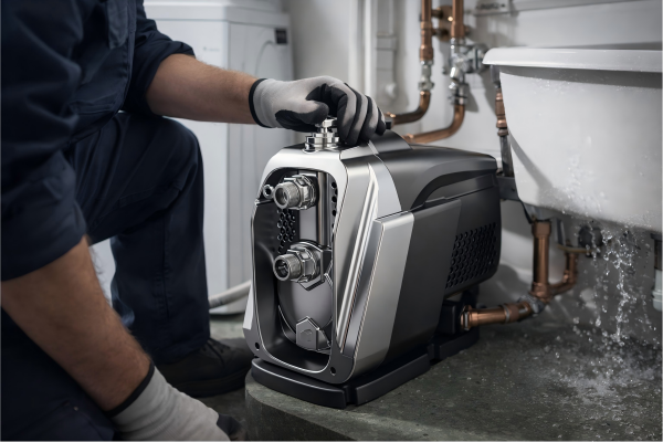
However, pumps are often installed in harsh environments like damp basements, dusty utility rooms, or outdoor locations exposed to humidity and temperature swings.
These conditions are the natural enemy of electronics.
Moisture can cause short circuits, dust can lead to overheating, and vibrations can loosen connections over time.
Recognizing this vulnerability, cutting-edge pump designs employ an uncompromising solution to guarantee electronic reliability: full potting of the Printed Circuit Board (PCB).
Total Environmental Sealing: The UltraShield PCB Potting
Potting is a process where the entire electronic assembly is encased in a solid, non-conductive compound.
This creates an impenetrable barrier that isolates the electronics from the outside world.
-
How It Works: The controller's PCB is placed in a mold, which is then filled with a liquid potting material, typically a type of epoxy or silicone. This material flows around every component, and once cured, it hardens into a solid block, creating a permanent, hermetic seal.
-
The Benefits of Sealing: This technique provides several critical advantages that directly enhance the product's long-term durability.
The Protective Advantages of a Potted Controller
The decision to pot the electronics is a direct investment in the product's lifespan and reliability.
| Protection Feature | Description | Impact on Reliability |
|---|---|---|
| 100% Waterproof | The seal is complete and seamless, achieving an IP67 rating for the electronics. This means the controller is protected against full water immersion. | It becomes impervious to moisture, condensation, humidity, and even accidental splashes or leaks, preventing 95% of moisture-related failures. |
| Dust and Debris Proof | The solid block prevents any dust, dirt, insects, or other small debris from ever reaching the electronic components. | This eliminates the risk of short circuits caused by conductive dust and prevents overheating caused by insulating layers of dirt. |
| Vibration Damping | The solid compound holds every component firmly in place, absorbing mechanical shocks and vibrations from the motor and plumbing system. | This prevents solder joints from failing and component legs from breaking due to long-term vibration, a common failure point in industrial electronics. |
By implementing this total protection strategy, the lifespan of the controller is projected to increase by 3 to 5 years.
It is a testament to a design philosophy that prioritizes robust engineering over cutting costs, ensuring that the pump's intelligence is comprehensively shielded for years of reliable operation.
This transforms the controller from a fragile component into a rugged, resilient core.
The "14-Shield": A Comprehensive Suite of Protection Functions
Do you worry about your pump being damaged by unseen problems?
Issues like running dry, voltage spikes, or overheating can destroy a pump without warning, leading to expensive and unexpected system failure.
An intelligent pump protects itself.
With a comprehensive suite of built-in software and hardware protections, the pump actively monitors for dangerous conditions.
It can shut itself down before damage occurs and even attempt to resolve issues automatically, safeguarding your investment.
The true intelligence of a modern VFD pump lies in its ability to protect itself.
A powerful motor and a durable body are useless if the system cannot defend itself against the many potential hazards of real-world operation.
The "14-Shield" protection system is a comprehensive software and hardware safety net that constantly monitors the pump's vital signs and the surrounding conditions.
This system is designed to anticipate, prevent, and respond to a wide range of faults, ensuring both the longevity of the pump and the safety of the entire water system.
It is like having a dedicated technician on duty 24/7, watching over your investment.
Categories of Protection
The protections can be grouped into several key areas, each defending against a different type of threat.
Electrical & Thermal Protections
This group of safeguards focuses on the quality of the electrical supply and the management of heat, which are two of the most common causes of electronic failure.
- Input Voltage Protection: The pump will shut down if the incoming voltage is too high or too low, protecting the electronics from damage caused by grid instability.
- Overcurrent and Stall Protection: If the motor draws too much current, either from a blockage or an electrical fault, the system will stop to prevent the motor windings from burning out.
- Overheating Protection: Multiple sensors monitor the temperature of the driver board (PCB), the motor, and the water itself. If any temperature exceeds a safe limit, the pump will stop and wait to cool down.
System & Sensor Protections
This group focuses on operational issues and the health of the monitoring system itself.
| Protection Function | Description | Benefit |
|---|---|---|
| Water Shortage (Dry Run) | This is the most critical pump protection. It detects when there is no water to pump. | Prevents the pump from overheating and destroying its mechanical seals, a common and catastrophic failure. |
| Antifreeze Protection | In cold climates, the pump will automatically circulate water for a short period when temperatures approach freezing. | Prevents ice from forming inside the pump housing, which could crack the casing and cause irreparable damage. |
| Pipeline Leak Warning | The system monitors for small, persistent pressure drops that indicate a leak in the plumbing. | Alerts the user to a potential leak, saving water and preventing costly water damage to the property. |
| Sensor Failure Warnings | The VFD continuously self-diagnoses its sensors. If a pressure or temperature sensor fails, it provides a specific error code. | Allows for quick and accurate troubleshooting, reducing downtime and repair costs. |
Smart Recovery from Dry Run
The dry run protection is particularly intelligent.
Instead of just shutting down permanently, it employs a multi-stage recovery algorithm.
If it senses a water shortage, it will stop and wait for a period, then try again.
The waiting period gets progressively longer with each attempt.
This allows the system to recover automatically if water supply is restored (e.g., a well refilling), without requiring manual intervention, while also conserving energy during extended outages.
This comprehensive shield makes the pump a truly robust and self-sufficient piece of equipment.
Intuitive User Interface and Real-Time Monitoring
Are complex controls making your high-tech equipment difficult to use?
Complicated menus and confusing indicators can make it impossible for users to operate or troubleshoot their pump effectively.
Simplicity is key to a good user experience.
A well-designed interface with simple button controls and clear LED indicators allows anyone to operate the pump, adjust settings, and understand its status at a glance, without needing to consult a manual for basic tasks.
For all its internal complexity, a modern VFD booster pump must be simple and intuitive for the end-user to operate.
Advanced technology is only useful if it is accessible.
A well-designed user interface (UI) bridges the gap between the sophisticated control system and the person using it, providing both straightforward control and deep insight into the pump's real-time performance.
The design philosophy is to make basic operations effortless while keeping powerful diagnostic data just a button-press away for technicians or curious homeowners.
This is achieved through a combination of tactile buttons, multi-function displays, and clear, color-coded LED indicators.
Effortless Operation for Everyday Use
The day-to-day functions are designed to be as simple as possible, requiring no technical knowledge.
- Simple Controls: The interface typically features a minimal number of buttons to avoid confusion.
- Power On/Off: A single short press of the power button turns the pump on or off.
- Pressure Adjustment: Dedicated "UP" and "DOWN" buttons allow the user to easily increase or decrease the target water pressure to their preference.
- Factory Reset: For troubleshooting, a long press of the power button can restore the system to its original default settings.
This streamlined approach ensures that anyone can manage the pump's primary functions without any special training.
Deep Diagnostics for Advanced Users
Beyond the simple controls, the interface provides a window into the pump's live operational data.
This is invaluable for monitoring performance and diagnosing any potential issues.
A long press of a specific button allows the user to cycle through a series of key real-time parameters displayed on the screen.
| Display Code | Parameter Being Measured | Why It's Useful |
|---|---|---|
| A.xx | Water Temperature | Helps diagnose issues related to hot water supply or overheating conditions. |
| P.xxx | Real-time Power (Watts) | Shows exactly how much energy the pump is consuming, highlighting the efficiency of VFD control. |
| xxxx | Motor Speed (RPM) | Provides direct feedback on how hard the pump is working to meet the current water demand. |
| U.xxx | Input Voltage | Allows the user to check for power grid instability that could affect pump performance. |
| t.xx | PCB Temperature | A critical diagnostic tool for monitoring the health of the electronic controller. |
At-a-Glance Status Indicators
For immediate feedback, a row of distinct LED lights provides the system's status without needing to read the display.
These indicators instantly tell the user about the pump's current state.
For example, there are dedicated lights to show:
- Constant Pressure Mode: A green light indicating the pump is running normally.
- Water Shortage: A red or amber light that flashes to alert the user that the pump has stopped due to lack of water.
- Voltage Fault: An indicator to warn of problems with the incoming electrical supply.
- Pipeline Leakage: A specific warning light for the system's leak detection function.
This multi-layered approach to the UI makes the pump both incredibly easy to use and a powerful tool for system monitoring, satisfying the needs of both the novice user and the professional installer.
Conclusion
In summary, a VFD is a highly intelligent type of inverter.
It provides precise motor control, delivering superior performance, energy efficiency, and equipment protection for applications like modern water pumps.
FAQs
What is the main difference between an inverter and a drive?
An inverter converts DC to AC power.
A drive (VFD) is a complete system that uses an inverter to precisely control a motor's speed and torque.
Is an AC drive the same as a VFD?
Yes, in the industrial context, the terms AC drive, Variable Frequency Drive (VFD), and inverter drive are used interchangeably to describe the same motor controller.
Can a VFD be used as an inverter?
While a VFD contains an inverter, it is not designed for general-purpose DC-to-AC conversion.
It is specifically built to control an AC motor.
What is the main function of a VFD?
The primary function of a VFD is to control the speed of an AC electric motor by adjusting the frequency of the electrical power supplied to it.
Can I use an inverter to control motor speed?
A simple inverter cannot control motor speed as it outputs a fixed frequency.
You need a Variable Frequency Drive (VFD) for speed control.
Does a VFD convert AC to DC?
Yes, the first stage of a VFD is a converter (rectifier) that changes the incoming AC power from the grid into DC power for its internal DC bus.
What are the three main sections of a VFD?
A VFD consists of three main sections: the Converter (AC to DC), the DC Bus (filters and stores power), and the Inverter (DC to variable AC).
Why use a VFD on a pump?
Using a VFD on a pump maintains constant water pressure, provides significant energy savings, and reduces mechanical stress by enabling soft starts and stops.