Struggling to calculate pressure for high-head applications?
A multistage pump has no single formula.
Instead, its performance is a sum of its parts.
The total head is the head per stage multiplied by the number of stages, while the flow rate remains constant.
Understanding this core principle is the first step.
It unlocks the ability to specify a pump that perfectly matches demanding high-pressure requirements.
Many engineers and distributors believe complex calculations are needed for every aspect of a multistage pump.
This can lead to confusion and incorrect specifications.
Let's break down the essential formulas into manageable parts.
You'll soon see how these individual calculations combine to define the pump's total performance.
The Core Concept: Understanding Total Head in Multistage Pumps
High-pressure tasks need more than a standard pump.
Failing to generate enough head means your system won't work.
This leads to project delays and unhappy clients.
A multistage pump's primary formula calculates Total Head.
It is simply the head generated by a single stage (one impeller) multiplied by the total number of stages in the pump.
This additive principle is what allows multistage pumps to achieve incredibly high pressures.
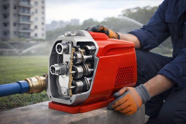
While a single-stage pump is limited by the physics of its single impeller, a multistage pump neatly bypasses this limitation.
It does so by essentially stacking pumps in a series within a single casing.
Each stage gives the fluid an energy boost, increasing its pressure before passing it to the next.
This sequential pressurization is the secret to their performance.
Let's explore the components of this crucial calculation.
What is Head?
Head is a fundamental concept in fluid dynamics.
It's a way to measure the energy of a fluid, specifically a pump's ability to move that fluid.
It is expressed as a height, typically in meters or feet.
If a pump has a total head of 50 meters, it can theoretically lift a column of water 50 meters straight up.
Head accounts for three types of energy:
- Elevation Head: The vertical height the fluid needs to be lifted.
- Pressure Head: The pressure the pump must overcome in a pressurized vessel.
- Friction Head: The energy lost due to friction as the fluid moves through pipes and fittings.
Calculating Head Per Stage
The head per stage is determined by a single impeller's design.
Key factors include the impeller's diameter, its rotational speed (RPM), and the shape and number of its vanes.
A larger diameter or a higher speed generally results in more head per stage.
For a specific pump model, the manufacturer's performance curve provides this information.
The curve shows how much head one stage can produce at a given flow rate.
For example, at a flow rate of 10 m³/h, a specific impeller might produce 20 meters of head.
The Total Head Formula
The formula itself is straightforward and powerful.
It is the foundation of multistage pump specification.
Total Head (H_total) = Head per Stage (H_stage) × Number of Stages (n)
Let's use a practical example to illustrate this.
| Variable | Value | Description |
|---|---|---|
| Required Total Head | 120 meters | The total vertical lift and friction loss for the application. |
| Head per Stage | 20 meters | The performance of one impeller at the desired flow rate. |
| Number of Stages | ? | The value we need to calculate. |
To find the number of stages, you rearrange the formula:
Number of Stages (n) = Total Head (H_total) / Head per Stage (H_stage)
So, for our example:
n = 120 meters / 20 meters = 6 stages
This means a 6-stage version of this pump model is required to meet the application's demands.
This calculation is vital for importers and distributors to correctly match a client's requirements with the right product configuration.
Flow Rate Consistency: The Unchanging Variable
Have you ever assumed that adding more stages increases the flow rate?
This common misconception leads to misapplication and system inefficiency.
More stages do not mean more volume.
The flow rate of a multistage pump is determined by its first impeller and remains constant through all subsequent stages.
The pump's design ensures the same volume of liquid passes through each stage sequentially.
Think of it like a single-lane highway.
The number of cars (flow rate) that can pass a certain point per hour is fixed.
You can add hills (head/pressure), but you can't magically fit more cars onto that single lane.
Each impeller is designed to handle a specific volume of fluid.
The first impeller draws in this volume.
It then passes that exact same volume to the second impeller, which passes it to the third, and so on.
There is nowhere for the fluid to go except to the next stage.
This principle is critical for understanding pump performance curves and for system design.
Why Flow Rate Stays the Same
Multistage pumps are essentially several single-stage pumps connected in series.
In any series circuit, the current (or flow) remains constant throughout.
The same applies here.
The fluid is incompressible.
The volume that enters the first stage must be the same volume that exits the final stage.
Each impeller is sized identically within a given pump model.
They are optimized to work together at a specific Best Efficiency Point (BEP) for flow.
Adding more stages doesn't change the size of the "doorway" that the fluid passes through.
The Role of Impeller Design
The impeller's design dictates the flow rate.
Specifically, the width of the impeller vanes and the size of the impeller "eye" (the inlet) are the primary factors.
A wider impeller with a larger eye will allow for a higher flow rate.
A narrower impeller is designed for lower flow rates.
This is why, for a given pump family, you might see different models for high-flow/low-head versus low-flow/high-head applications.
The number of stages only affects the final pressure, not the volume handled per minute or hour.
Factors That Can Affect Flow Rate
While the number of stages doesn't change the flow rate, other system factors do.
The pump's performance curve will show you exactly how system changes impact flow.
- Total System Head: If the actual system head (from pipes, valves, elevation) is higher than you calculated, the pump will operate at a point further back on its curve, resulting in a lower flow rate.
- Pipe Diameter: Using pipes that are too small increases friction loss dramatically. This adds to the system head and reduces the flow.
- Rotational Speed (RPM): For pumps paired with a Variable Frequency Drive (VFD), reducing the speed will reduce both the flow rate and the head, according to the Affinity Laws. For example, a 20% reduction in speed results in a 20% reduction in flow.
- Suction Conditions: Poor suction conditions, or insufficient Net Positive Suction Head (NPSH), can cause cavitation. This leads to vapor bubbles forming and collapsing, which severely disrupts flow and damages the pump.
Understanding that flow is a constant allows you to focus on the real variable you are controlling: pressure.
Calculating Power Requirements: The Engine of the Pump
Under-powering a pump is a recipe for disaster.
An undersized motor will overheat and fail, causing costly downtime.
You must accurately calculate the power needed to drive the pump.
The power required for a multistage pump depends on the total head, the flow rate, the fluid's specific gravity, and the pump's overall efficiency.
A formula for Brake Horsepower (BHP) is used to determine the necessary motor size.
As you add stages to a pump, the total head increases.
Doing more work (lifting water higher) requires more energy.
Therefore, a pump with more stages requires a more powerful motor than one with fewer stages, even at the same flow rate.
Efficiency plays a huge role.
A pump that is 80% efficient will require significantly less power than one that is only 60% efficient to do the same amount of work.
This directly impacts long-term operational costs.
Let's examine the formula and its components more closely.
Brake Horsepower (BHP) Explained
Brake Horsepower (BHP) is the actual power delivered to the pump shaft from the motor.
It is the power required to overcome both the work done on the fluid and the internal energy losses within the pump (due to friction and hydraulic inefficiencies).
This is different from Water Horsepower (WHP), which is only the power transferred to the fluid itself.
When selecting a motor, you must ensure its rated horsepower is greater than the calculated BHP, providing a safety margin. A service factor of 1.15 is common, meaning a motor can be run at 15% above its rated power.
The BHP Formula
The standard formula to calculate the required power is as follows:
BHP = (Q × H × SG) / (3960 × η)
Where:
- Q = Flow Rate (in US Gallons Per Minute, GPM)
- H = Total Head (in feet)
- SG = Specific Gravity of the fluid (for water, this is 1.0)
- 3960 = A conversion constant for US customary units
- η = Pump Efficiency (as a decimal, e.g., 75% is 0.75)
For metric units, the formula is:
Power (kW) = (Q × H × SG) / (367 × η)
Where:
- Q = Flow Rate (in cubic meters per hour, m³/h)
- H = Total Head (in meters)
- SG = Specific Gravity (1.0 for water)
- 367 = A conversion constant for metric units
- η = Pump Efficiency (as a decimal)
Efficiency's Critical Role
Pump efficiency (η) is a crucial factor.
It represents the ratio of the power delivered to the fluid versus the power supplied to the pump shaft.
No pump is 100% efficient; some energy is always lost.
A pump's efficiency varies with its flow rate.
It is highest at its Best Efficiency Point (BEP).
Operating a pump far from its BEP not only wastes energy but also increases wear and tear, leading to a shorter operational life.
Consider this example with changing stage numbers and efficiency.
| Number of Stages | Total Head (m) | Flow Rate (m³/h) | Efficiency (η) | Required Power (kW) |
|---|---|---|---|---|
| 4 States | 80 m | 20 m³/h | 0.75 | 5.8 kW |
| 6 Stages | 120 m | 20 m³/h | 0.75 | 8.7 kW |
| 8 Stages | 160 m | 20 m³/h | 0.72 | 12.2 kW |
Notice how the required power increases directly with the head.
Also note that in some cases, adding more stages can slightly decrease overall efficiency, further increasing power demand.
Always consult the manufacturer's data to select a motor that meets the power requirements at the pump's duty point.
Net Positive Suction Head (NPSH): Preventing Catastrophic Failure
Ignoring suction conditions can destroy a pump in minutes.
If the pump starves for fluid, it can lead to cavitation, a highly destructive phenomenon.
This results in severe damage and complete pump failure.
NPSH is not a single formula, but a critical comparison.
The Net Positive Suction Head Available (NPSHA) from your system must be greater than the Net Positive Suction Head Required (NPSHR) by the pump.
Think of NPSHA as the "push" your system gives the fluid to get it into the pump's first stage.
Think of NPSHR as the minimum "push" the pump needs to avoid forming vapor bubbles.
If the push available is less than the push required, the liquid will essentially boil at the impeller eye, even at room temperature.
This is called cavitation.
The collapse of these vapor bubbles releases immense energy, which chips away at the impeller material, sounding like gravel is passing through the pump.
NPSHA vs. NPSHR
NPSHA (Available): This value is calculated based on your specific system installation.
It is a function of the atmospheric pressure, the height of the liquid source relative to the pump, the vapor pressure of the liquid, and the friction losses in the suction piping.
NPSHA = Atmospheric Pressure Head - Vapor Pressure Head +/- Static Suction Head - Friction Head
NPSHR (Required): This value is an intrinsic characteristic of the pump itself.
It is determined by the pump manufacturer through testing.
It represents the minimum pressure required at the pump's suction port to prevent cavitation.
This value is found on the pump's performance curve and typically increases with the flow rate.
The Dangers of Cavitation
Cavitation is one of the most significant causes of pump failure.
The consequences are severe and costly.
- Impeller Damage: The implosion of vapor bubbles creates micro-jets that erode the impeller surface, leading to pitting and eventual destruction.
- Performance Loss: The presence of vapor disrupts the smooth flow of liquid, causing a sharp drop in both head and flow rate.
- Excessive Vibration and Noise: A cavitating pump runs erratically and loudly, placing extreme stress on bearings, seals, and the motor.
- Complete Failure: If left unaddressed, cavitation will lead to catastrophic failure of the pump's core components.
A safety margin is crucial.
It is recommended that NPSHA be at least 1.5 to 2 times greater than NPSHR to ensure safe, quiet, and reliable operation.
Does NPSH Change with Stages?
This is a key point for multistage pumps.
The NPSHR value is determined only by the design of the first stage impeller.
This is because the first stage is the only one operating under suction conditions from the system.
All subsequent stages receive fluid that is already pressurized by the preceding stage.
Therefore, they have more than enough pressure to avoid cavitation.
So, whether you have a 2-stage pump or a 20-stage pump of the same model, the NPSHR will be exactly the same.
Your focus remains solely on ensuring the system's NPSHA is sufficient for that first critical stage.
Putting It All Together: A Practical Calculation Example
Theory is good, but practical application is better.
Let's walk through a real-world scenario.
This will cement your understanding of how these formulas work together to specify the right multistage pump.
Let's design a multistage pump system for a boiler feed application.
The goal is to take water at a specific flow rate and boost its pressure sufficiently to inject it into a pressurized boiler, overcoming all height and friction losses.
This process combines everything we've discussed.
We will start with the system's requirements and end with the final pump and motor specification.
This is the exact process an application engineer would follow.
It transforms a set of demands into a tangible hardware solution.
By following these logical steps, you eliminate guesswork and ensure the equipment selected is perfectly suited for the job.
Let's begin with the known variables.
Step 1: Define the Requirements
First, we must know what the system needs to accomplish.
This data is the foundation for all subsequent calculations.
| Parameter | Value (Metric) | Value (US) | Description |
|---|---|---|---|
| Required Flow Rate (Q) | 45 m³/h | ~200 GPM | The volume of water the boiler needs per hour. |
| Boiler Pressure | 12 bar | ~174 PSI | The pressure inside the boiler that must be overcome. |
| Static Lift | 15 meters | ~49 feet | The vertical height from the pump to the boiler inlet. |
| Friction Loss | 8 meters | ~26 feet | The calculated head loss from pipes, valves, and elbows. |
| Fluid | Water | Water | Specific Gravity (SG) = 1.0. |
Step 2: Calculate Total Head Needed
Now, we add up all the pressure and height requirements to find the total head the pump must generate.
Remember to convert the boiler pressure into head.
1 bar ≈ 10.2 meters of head.
1 PSI ≈ 2.31 feet of head.
Total Head (H_total) = Pressure Head + Static Lift + Friction Loss
H_total (Metric) = (12 bar × 10.2 m/bar) + 15 m + 8 m
H_total (Metric) = 122.4 m + 15 m + 8 m = 145.4 meters
We will round this up to 146 meters for our calculation.
Step 3: Determine the Number of Stages
Next, we consult a manufacturer's pump curve for a model that can handle a flow rate of 45 m³/h efficiently.
Let's say we find a pump where, at 45 m³/h, a single stage produces 25 meters of head.
Now we apply the head formula.
Number of Stages (n) = Total Head / Head per Stage
n = 146 meters / 25 meters = 5.84 stages
Since we cannot have a fraction of a stage, we must round up to the next whole number.
Required Stages = 6
A 6-stage version of this pump will provide: 6 stages × 25 m/stage = 150 meters of total head, which safely exceeds our requirement of 146 meters.
Step 4: Calculate the Required Power
Finally, we calculate the motor power needed for our 6-stage pump.
We look at the pump curve again and find that at our duty point (45 m³/h @ 150 m), the pump efficiency (η) is 78% (or 0.78).
Using the metric BHP formula:
Power (kW) = (Q × H × SG) / (367 × η)
Power (kW) = (45 × 150 × 1.0) / (367 × 0.78)
Power (kW) = 6750 / 286.26 = 23.58 kW
The required power is 23.58 kW.
We must select the next standard-sized motor that is larger than this value.
The next standard size is typically 30 kW.
This provides a safe operating margin and ensures the motor will not be overloaded.
Our final specification is a 6-stage pump coupled with a 30 kW motor.
Conclusion
Mastering these core formulas transforms multistage pump selection from a guess into a science.
Focus on total head, power, and NPSH to ensure optimal performance and reliability.
FAQs
1. How do you calculate the head of a multistage pump?
The total head is the head produced by one stage (impeller) multiplied by the total number of stages. This result must meet the system's pressure and height requirements.
2. What is the formula for pump power calculation?
The formula for brake horsepower (BHP) is (Flow Rate × Total Head × Specific Gravity) / (Constant × Pump Efficiency). The specific constant depends on the units being used.
3. Does flow rate increase in a multistage pump?
No, the flow rate remains constant. It is determined by the size and design of the first stage impeller and stays the same through all subsequent stages of the pump.
4. How many stages can a multistage pump have?
Multistage pumps can have many stages, sometimes over 50. The exact number depends on the required discharge pressure and the head generated by each individual stage.
5. What is the efficiency of a multistage pump?
The efficiency varies but typically ranges from 60% to over 80%. It is highest at the Best Efficiency Point (BEP) and is listed on the manufacturer's performance curve.
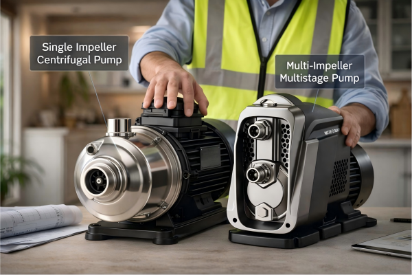
6. What is the main difference between single-stage and multistage pumps?
A single-stage pump has one impeller and is for lower-pressure applications. A multistage pump has multiple impellers in series to achieve much higher discharge pressures.
7. Why is NPSH important for multistage pumps?
Sufficient NPSH is critical to prevent cavitation in the first stage. Cavitation can quickly destroy the pump's impeller and lead to catastrophic failure of the entire unit.
8. Can I use a VFD with a multistage pump?
Yes, using a Variable Frequency Drive (VFD) is an excellent way to control a multistage pump. It allows for precise adjustment of speed to match system demand, saving significant energy.