Your pump is running, but no water is coming out.
This frustrating situation often points to one culprit: air in the system, which can cause costly damage and operational failure.
A centrifugal pump cannot handle air because air is about 800 times less dense than water.
The pump's impeller is designed to throw heavy liquid outward to create suction, but it cannot generate enough force to move lightweight air, causing an "airlock" that stops all flow.
This phenomenon, known as airlock or vapor lock, is a fundamental limitation of centrifugal pump design.
Pumps are engineered for incompressible liquids, not compressible gases like air.
When a pump encounters air instead of liquid, it loses its ability to create the pressure difference necessary for suction.
The impeller just spins in the air, unable to grip it and move it along.
This isn't just an efficiency problem; it can lead to serious mechanical damage from overheating and vibration.
Understanding the specific reasons why air is the enemy of your pump is the first step toward preventing these costly failures and ensuring the reliability of your water systems.
In this article, we'll break down the physics behind this common issue and explain what happens inside your pump when it encounters air.
Why Air Is the Enemy of Your Pump
Is your pump suddenly failing to move water, even though the motor is running perfectly?
This common issue is often caused by air entering the suction line, a problem that renders the pump useless.
A centrifugal pump fails with air because its impeller is designed for dense liquids, not light gases.
Air is not heavy enough for the impeller to create the centrifugal force needed to generate pressure and suction, effectively stopping the pump's operation and preventing liquid from entering.
A pump's ability to create pressure is directly tied to the density of the fluid it is moving.
This relationship is a core principle of fluid dynamics.
The entire design of a centrifugal pump is optimized for the physical properties of liquids like water.
When a much lighter substance like air is introduced, the pump's mechanics can no longer function as intended.
It's like trying to throw a feather with the same force you'd use to throw a stone; the feather simply won't travel far.
This section explores the fundamental science behind this limitation, focusing on how mass and density are critical for pump performance.
The Physics of Pumping: Mass and Density
The core function of a centrifugal pump is to convert rotational energy from a motor into kinetic energy in a fluid.
An impeller, which is a rotor with vanes, spins rapidly.
This spinning action imparts velocity to the liquid, throwing it outward toward the pump casing (volute) due to centrifugal force.
As the liquid is forced away from the center, it creates a low-pressure zone at the "eye" of the impeller.
This pressure difference between the pump inlet and the atmosphere or source tank is what creates suction, drawing more liquid into the pump.
This process depends entirely on the mass of the fluid being moved.
Why Air Fails the Test
Air is approximately 800 times less dense than water.
When the impeller tries to throw air, it simply cannot generate a meaningful centrifugal force because the air has very little mass.
The air swirls around inside the casing without being effectively expelled.
Consequently, the low-pressure zone at the impeller eye never forms.
Without this low-pressure zone, the pump loses its ability to create suction.
No new liquid can be drawn into the pump, and the entire pumping action ceases, even if the impeller is spinning at thousands of RPM.
The Head Formula Explains It All
The pressure, or "head," that a pump can generate is calculated using a fundamental formula.
Understanding this helps clarify why density is so important.
| Variable | Description | Impact of Air vs. Water |
|---|---|---|
| P | Pressure | This is the output we want the pump to generate. |
| ρ (rho) | Fluid Density | For water, this value is high. For air, it is extremely low. |
| g | Gravity | A constant value. |
| h | Height | The height the fluid can be lifted, also known as head. |
The formula is P = ρgh.
This equation shows that the pressure (P) is directly proportional to the density (ρ) of the fluid.
If you reduce the density (ρ) by a factor of 800 by introducing air, the pressure (P) the pump can generate drops by the same factor.
This minuscule pressure is not enough to overcome even the slightest resistance or lift water even a few centimeters, rendering the pump ineffective.
The Science of Airlock and Lost Suction
Your pump is running smoothly, but suddenly the flow stops completely.
This frustrating "airlock" condition traps air at the pump's core, creating a barrier that blocks all liquid from entering.
Airlock occurs when air bubbles accumulate in the eye of the impeller, forming a pocket of gas the pump cannot move.
This gas bubble breaks the continuous column of liquid required for suction, effectively vapor-locking the pump and preventing it from priming or moving fluid.
Airlock is one of the most common and misunderstood failure modes in centrifugal pump operation.
It is not a mechanical failure in the traditional sense but a hydraulic one.
The pump is mechanically sound, but the presence of air makes it physically incapable of performing its function.
The air bubble becomes trapped by the spinning impeller, and because it's so light, the impeller's vanes slice right through it without being able to force it out through the discharge port.
This stubborn bubble sits at the very point where suction is supposed to be created, effectively building a wall against incoming liquid.
Let's explore the causes and mechanisms of this critical issue.
How Does Airlock Happen?
Air can enter a pumping system in several ways, all leading to the same frustrating outcome.
Recognizing these sources is key to prevention.
- Leaks in the Suction Line: This is the most common cause. Even a tiny pinhole leak in the suction hose, pipe, or fittings can allow air to be drawn into the system. Since the suction side is under negative pressure (a vacuum), it will pull air in rather than leak water out.
- Low Water Level: If the water level in the source tank or sump drops below the suction inlet, the pump will start pulling in air along with the water.
- Dissolved Gases: Water can contain dissolved gases, especially if the water temperature rises or pressure drops suddenly. These gases can come out of the solution inside the suction line, forming bubbles that coalesce at the impeller.
- Improper Priming: A pump must be fully filled with liquid (primed) before it is started. If any air pockets are left in the pump casing or suction line during priming, they can lead to an immediate airlock.
The Vicious Cycle of Lost Suction
Once an air bubble forms at the impeller eye, a destructive cycle begins.
The pump is no longer moving liquid, so there is no flow through the system.
However, the motor is still running, and the impeller is still spinning at high speed.
This situation leads to several other problems.
The small amount of liquid that might be trapped in the casing with the air gets churned repeatedly.
This churning action generates friction and heat, which can cause the water to flash into steam, worsening the vapor lock.
Breaking the Lock
To resolve an airlock, you must stop the pump and re-prime the system.
This involves several steps.
- Turn Off the Pump: Continuing to run an air-locked pump will lead to damage.
- Identify and Fix the Source: Find and repair any leaks in the suction line. Ensure the suction inlet is sufficiently submerged.
- Vent the Air: Open the priming plug or a vent valve on the top of the pump casing to allow the trapped air to escape.
- Re-prime the System: Slowly fill the pump casing and the suction line with liquid until all air has been expelled and a solid stream of water flows from the vent.
- Restart the Pump: Once the system is fully primed, you can safely restart the pump.
Preventing air from entering the system in the first place is always the best strategy.
Regular inspection of suction-side components is essential for reliable pump operation.
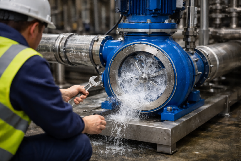
The Damaging Effects: Cavitation and Dry Running
Have you ever heard your pump making a noise like it's gargling gravel?
This alarming sound is a sign of cavitation, a destructive process that can quickly destroy your pump's internal components.
When a pump is starved of liquid due to airlock, it can lead to two severe conditions: cavitation and dry running.
Cavitation is the formation and collapse of vapor bubbles, causing intense shockwaves.
Dry running is when the impeller spins without liquid, causing extreme overheating from friction.
While an air-locked pump is inefficient, the real danger comes from the secondary effects that occur when the pump continues to operate without liquid.
The energy from the motor has to go somewhere.
Instead of moving fluid, that energy is converted into heat, noise, and destructive vibrations.
These forces can cause rapid and catastrophic failure of the pump's most critical parts, leading to expensive repairs and significant downtime.
Understanding the mechanisms of cavitation and dry running highlights why preventing air in your pump is not just about performance, but about protecting your investment.
Cavitation: The Sound of Destruction
Cavitation is a complex phenomenon that can be caused by air or insufficient suction head.
When air bubbles that were drawn into the pump finally move from the low-pressure eye of the impeller to the high-pressure area at the edge of the vanes, they collapse violently.
This collapse is not a gentle pop.
It's an implosion that creates a microscopic but incredibly powerful shockwave.
Thousands of these implosions happening every second generate the characteristic "gravel" sound.
These shockwaves act like tiny hammer blows against the surface of the impeller and pump casing.
This continuous assault can physically chip away at the metal, causing pitting and erosion that destroys the precise hydraulic surfaces of the components.
The consequences of cavitation are severe.
- Component Damage: The impeller and volute can be eroded to the point of failure.
- Increased Vibration: The violent bubble collapse creates significant vibration, which can damage bearings and mechanical seals.
- Reduced Performance: A cavitating pump cannot operate at its designed efficiency, leading to reduced flow and pressure.
- Noise: The loud, damaging noise is a clear indicator of a serious operational problem.
Dry Running: The Silent Killer
Airlock leads directly to a condition called "dry running."
This occurs when there is no liquid flowing through the pump to lubricate and cool its moving parts.
The impeller spins at thousands of RPM in a casing filled mostly with air.
This scenario creates two major problems.
- Overheating: Centrifugal pumps rely on the fluid they are pumping to carry away the heat generated by the motor and the friction of the rotating parts. Without this cooling flow, temperatures inside the pump can rise very quickly. This heat can melt plastic components, destroy the mechanical seal, and cause the motor to overheat and fail.
- Lack of Lubrication: The mechanical seal, which prevents water from leaking out along the motor shaft, requires a thin film of liquid for lubrication. During dry running, this seal runs dry, causing rapid wear and failure. A failed seal will leak, and can also lead to water entering the motor bearings, causing them to rust and seize.
Modern intelligent pumps often include built-in protections against these conditions.
| Protection Feature | How It Works |
|---|---|
| Dry Run Protection | A sensor detects a drop in power consumption or a loss of pressure, automatically shutting down the pump to prevent damage. It may then try to restart after a set period. |
| Overheating Protection | Temperature sensors on the motor windings and driver board monitor for excessive heat, shutting the pump off before permanent damage occurs. |
| Cavitation Detection | Advanced systems can analyze pressure fluctuations or vibration signatures to detect the onset of cavitation and alert the user or shut down the pump. |
These safety features are critical for extending the life of a pump and preventing catastrophic failures caused by air intrusion.
A Different Machine for a Different Job: Pumps vs. Compressors
You wouldn't use a screwdriver to hammer a nail.
Similarly, you can't use a centrifugal pump to move air effectively because it's the wrong tool for the job.
The confusion arises because centrifugal compressors and blowers, which look similar, are designed specifically to handle air and other gases.
Centrifugal pumps are for high-density, incompressible liquids, while centrifugal compressors are for low-density, compressible gases.
Their designs differ significantly in speed, clearances, and impeller shape to manage these fundamentally different media, making them non-interchangeable tools for different tasks.
At first glance, a centrifugal pump and a centrifugal compressor might seem like close relatives.
They both use a spinning impeller to impart energy to a fluid.
However, the fluids they are designed to handle—liquid versus gas—have drastically different physical properties.
These differences demand completely different engineering approaches.
A pump is a low-speed, high-pressure device designed to move a dense, non-compressible fluid.
A compressor or blower is a high-speed, lower-pressure device designed to move a light, compressible fluid.
Trying to use one for the other's job is not only inefficient but also dangerous.
Let's break down the key design distinctions that separate these two technologies.
Key Design Differences
The functional requirements for moving a liquid versus a gas lead to major variations in mechanical design.
Everything from the speed of rotation to the shape of the impeller is tailored for the specific medium.
| Feature | Centrifugal Pump (for Liquid) | Centrifugal Compressor/Blower (for Gas) |
|---|---|---|
| Operating Speed (RPM) | Low (e.g., 1,000 - 3,600 RPM) | Very High (e.g., 10,000 - 100,000+ RPM) |
| Fluid Density | High (e.g., 1000 kg/m³ for water) | Low (e.g., 1.2 kg/m³ for air) |
| Fluid Compressibility | Incompressible | Highly Compressible |
| Impeller Design | Narrow passages, fewer vanes | Wider passages, often with more complex, multi-stage vanes |
| Internal Clearances | Larger clearances between impeller and casing | Very tight clearances to prevent gas leakage |
| Pressure Ratio | High pressure increase in a single stage | Low pressure increase per stage; often requires multiple stages |
Why High RPMs are Needed for Air
As we've established, air has very little mass.
To impart enough energy to compress air and create meaningful flow, the impeller must spin at extremely high speeds.
This high velocity compensates for the air's low density.
A centrifugal blower running at 15,000 RPM can generate the force needed to move air effectively.
In contrast, a water pump running at a typical 2,900 RPM simply cannot spin fast enough to have any significant effect on air.
Running a water pump at the speeds required for a compressor would destroy its bearings and seals, which are not designed for such high velocities.
The Role of Tight Clearances
Gases are much "thinner" than liquids and can easily leak past moving parts.
Centrifugal compressors are built with very tight tolerances and clearances between the impeller and the casing.
This precise construction minimizes internal leakage, ensuring that the gas is forced through the intended flow path and pressure can be built efficiently.
Water pumps, which handle a much more viscous and dense fluid, can be built with larger, more forgiving clearances.
These larger clearances would allow far too much air to recirculate within a compressor, preventing it from building any pressure.
These fundamental design differences make it clear that pumps and compressors are specialized machines.
A centrifugal pump is a master of moving liquids but an absolute failure at moving air, simply because it was never designed for that purpose.
Conclusion
A centrifugal pump fails to handle air because its design relies on the high density of liquids.
Air is too light for the impeller to create the necessary force for suction.
FAQs
What happens if a centrifugal pump runs with air?
Running with air, known as dry running, causes the pump to overheat due to lack of cooling from liquid flow, which can quickly damage its seals and bearings.
How do you get air out of a centrifugal pump?
Stop the pump, open a vent or priming plug on the casing to let air escape, and slowly fill the pump and suction line with water until all air is gone.
Why does my pump get air lock?
Airlock is usually caused by leaks in the suction line, a low water level in the source tank, or improper priming that leaves air trapped in the system.
Can a centrifugal pump self-prime?
Most standard centrifugal pumps cannot self-prime. They must be manually filled with liquid before starting unless they are part of a special self-priming design with an external chamber.
What is the difference between air lock and vapor lock?
Airlock is caused by trapped air from an external source. Vapor lock is similar but caused by the liquid inside the pump turning into vapor (steam) due to excessive heat or low pressure.
How do you prevent air from getting into a pump?
Regularly inspect all suction-side pipes, hoses, and fittings for leaks. Ensure the suction inlet is always well below the water surface and prime the pump correctly before every use.
Can a little air damage a pump?
Yes, even a small amount of air can cause cavitation, which creates damaging micro-implosions that erode the impeller and reduce pump life and efficiency over time.
How does a self-priming centrifugal pump work?
A self-priming pump has a special casing design that traps a reserve of liquid. This liquid is used to create a vacuum that purges air from the suction line.