Struggling with pump failures and inefficient water flow?
These issues often stem from a poor understanding of the pump's core parts.
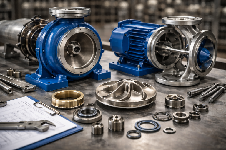
This guide provides a detailed breakdown of each component.
Understanding these parts is the first step toward selecting, operating, and maintaining a pump for optimal performance and longevity.
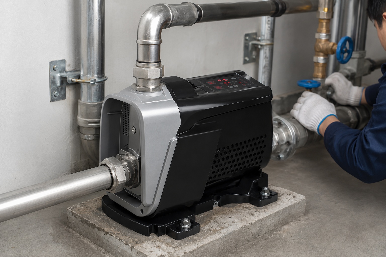
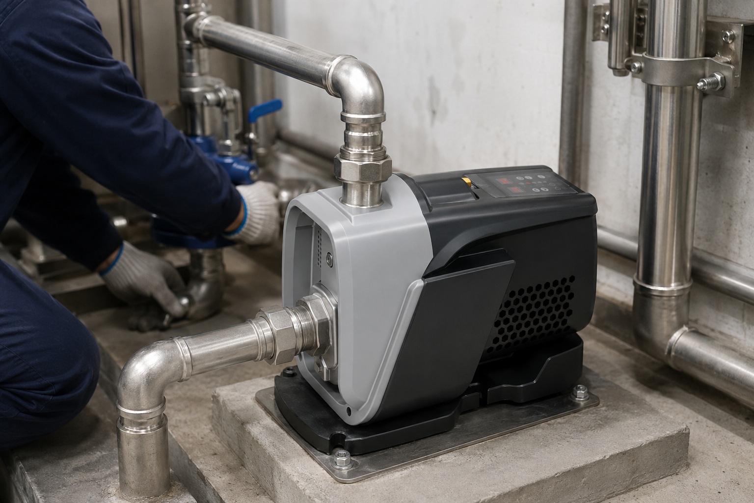
A centrifugal pump is a marvel of fluid dynamics, essential in countless applications from household water supply to large-scale industrial processes.
It uses rotational energy, typically from a motor, to move fluids.
At its heart, a rotating component called an impeller spins rapidly within a stationary housing called a casing.
This action creates centrifugal force, which pushes the fluid outwards at high velocity.
The casing then collects this high-velocity fluid and slows it down, converting the kinetic energy into pressure.
This pressure is what drives the fluid through the outlet and down the pipeline.
Grasping this fundamental principle is key to understanding how each individual component contributes to the pump's overall function and efficiency.
Let's explore these critical parts in more detail.
What is an Impeller?
Is your pump struggling to move liquids with solids?
The wrong impeller type could be causing clogs and inefficiency.
An impeller is the pump's rotating heart.
It has vanes that transfer energy from the motor to the fluid.
Its rapid rotation creates the centrifugal force needed to propel liquid outward, generating flow and pressure.
The right impeller design is critical for efficiency and handling specific fluid types.
Choosing the right impeller goes far beyond just moving water.
It's a critical engineering decision that directly impacts the pump's performance, efficiency, and ability to handle the specific liquid in your application.
The design and material of the impeller determine its suitability for everything from clean water to abrasive slurries or fluids with entrained gases.
Impeller Design Considerations
The physical shape of the impeller dictates its performance characteristics.
Engineers must balance flow rate, pressure (head), and solids-handling capability.
- Open Impellers: These impellers feature vanes attached to a central hub without any surrounding shroud.
This open design makes them excellent for handling liquids with high concentrations of suspended solids, like wastewater or slurry, as it reduces the risk of clogging. - Closed Impellers: These have vanes enclosed between two solid shrouds (a front and back plate).
This design is highly efficient for pumping clean liquids, as it minimizes recirculation and maximizes pressure development.
They are common in water supply and HVAC systems. - Semi-Open Impellers: This design is a hybrid, with vanes enclosed by a back shroud but open on the front side.
It offers a good compromise between the solids-handling ability of an open impeller and the efficiency of a closed one, making it useful in chemical processing and light industrial applications. - Vortex Impellers: Specifically recessed into the pump casing, this impeller type creates a vortex that moves the fluid, rather than the impeller making direct contact.
This is ideal for liquids with large solids, stringy materials, or significant entrained air, as most solids pass through without touching the impeller itself.
The Importance of Impeller Material
The material of an impeller is just as crucial as its design, determining its lifespan and resistance to wear and corrosion.
| Material | Primary Advantage | Common Applications |
|---|---|---|
| Cast Iron | Low cost, good for general use | Clean water circulation, general service |
| Bronze | Good corrosion resistance | Saltwater, brackish water, some chemicals |
| AISI 304 Stainless Steel | Excellent corrosion & abrasion resistance | Food processing, chemical transfer, water treatment |
| Hardened Alloys | Extreme abrasion resistance | Slurry pumping, mining applications |
Advanced pumps often utilize high-grade materials like AISI 304 stainless steel.
This choice provides superior durability against both chemical corrosion and the erosive effects of suspended particles, ensuring a longer operational life and consistent performance.
What is Casing?
Are you seeing reduced pump pressure and efficiency?
Your pump's casing might be mismatched for your application, causing energy loss.
The casing is the stationary housing that encloses the impeller.
It plays two critical roles: it directs the incoming fluid into the impeller's center and collects the high-velocity fluid leaving the impeller, converting this velocity into stable pressure.
The casing's design is vital for pump efficiency.
The casing is not just a simple cover.
It is a precisely engineered hydraulic component designed to manage the flow of energy within the pump.
As the impeller slings fluid outward at high speed, the casing's job is to efficiently contain this fluid and manage its energy conversion.
An improper casing design leads to turbulence, recirculation, and significant energy losses, which translates to lower pressure, reduced flow, and higher electricity bills.
Key Types of Casings
The internal geometry of the casing defines how it handles the fluid and its energy.
The two most common designs are volute and diffuser casings.
- Volute Casing: This is the most common type.
It features a spiral-shaped channel with a progressively increasing cross-sectional area.
As fluid exits the impeller and enters the volute, it slows down.
This decrease in velocity causes a corresponding increase in pressure, according to Bernoulli's principle.
Single volute designs are simple and effective, but they can create unbalanced radial forces on the shaft, especially when the pump operates away from its best efficiency point (BEP). - Double Volute Casing: To counteract the radial force issue, high-performance pumps often use a double volute casing.
This design features two separate volutes (a splitter wall divides the flow into two streams).
These two streams work to equalize the pressure forces acting on the impeller from opposite sides.
This balancing act dramatically reduces radial thrust, which in turn minimizes shaft deflection, reduces stress on bearings and seals, and extends the overall life of the pump. - Diffuser Casing: This design uses stationary vanes, known as a diffuser, positioned around the impeller.
These vanes form expanding passages that more gradually and efficiently slow the fluid down, converting kinetic energy into pressure.
Pumps with diffuser casings, often found in multistage pumps, can achieve higher efficiencies and pressures than standard volute designs.
Casing Construction and Material
The casing must be robust enough to contain the pressure generated within the pump and resist the corrosive or abrasive nature of the fluid being pumped.
Common materials include cast iron for general water service, stainless steel for corrosive fluids, and specialized alloys for abrasive slurries.
Modern pumps may also feature casings made from high-strength, UV-resistant polymers or ABS plastic, offering excellent durability and resistance to environmental degradation, especially for pumps installed outdoors.
Understanding Shaft and Bearings
Hearing grinding noises or feeling excess vibration from your pump?
Failing bearings or a misaligned shaft are likely culprits.
The shaft is the central component that transmits torque from the motor to the impeller, causing it to spin.
Bearings are crucial elements that support the shaft, holding it in correct alignment while allowing it to rotate smoothly with minimal friction.
They handle both radial and axial forces.
The shaft and bearing assembly forms the rotational backbone of the centrifugal pump.
A failure in either of these components will bring the entire system to a halt.
The shaft must be strong enough to handle the torque from the motor and the various forces exerted by the impeller without bending or breaking.
The bearings, in turn, are the unsung heroes that absorb these forces, ensuring the shaft spins true and with minimal energy loss due to friction.
The quality of these components directly influences the pump's reliability, lifespan, and operational quietness.
The Role of the Shaft
The pump shaft must be perfectly straight and balanced.
Any slight bend or imbalance will cause significant vibration during high-speed rotation.
This vibration not only creates noise but also accelerates wear on the bearings, mechanical seals, and wear rings, leading to premature failure.
Shafts are typically made from high-strength steel or stainless steel to resist corrosion and torsional stress.
The Critical Function of Bearings
Bearings manage the forces acting on the shaft during operation.
These forces come from two primary directions.
- Radial Forces: These forces act perpendicular to the shaft.
They are caused by the unbalanced hydraulic pressure within the casing and the weight of the impeller and shaft itself.
Radial bearings, such as deep-groove ball bearings, are designed to handle these loads. - Axial Forces (Thrust): These forces act parallel to the shaft, pushing it forward or backward.
They are generated by the pressure differences across the impeller.
Thrust bearings, like angular contact ball bearings, are used to manage these axial loads.
Top-tier pumps often use high-precision bearings from renowned manufacturers.
While they may look similar to standard bearings, these premium components offer tangible benefits.
| Feature | Premium Bearings | Standard Bearings |
|---|---|---|
| Precision | Higher manufacturing tolerances | Lower manufacturing tolerances |
| Noise Level | Significantly quieter operation | Can be a source of operational noise |
| Lifespan | Longer rated life under load | Shorter operational lifespan |
| Friction | Lower internal friction, higher efficiency | Higher internal friction |
Investing in pumps with high-quality bearings means less maintenance, quieter operation, and a longer service life, which translates to a lower total cost of ownership over time.
Seals in Centrifugal Pumps – An Overview
Is your pump constantly leaking fluid around the shaft?
This common problem indicates that your pump's sealing system is failing or inadequate.
A seal is essential for preventing the pumped liquid from leaking out of the casing where the rotating shaft passes through.
It contains the pressure within the pump, protects the bearings from contamination, and prevents environmental spills.
The two main types are packing seals and mechanical seals.
The sealing system is one of the most critical and often most vulnerable parts of a centrifugal pump.
It must create a near-perfect seal between the stationary casing and the rapidly rotating shaft, a challenging task that involves managing pressure, temperature, and friction.
A leaking seal isn't just a messy inconvenience; it reduces pump efficiency, can lead to bearing failure if the leaked fluid enters the housing, and can pose a safety or environmental hazard if the fluid is corrosive or toxic.
Traditional vs.
Modern Sealing Solutions
For decades, the standard sealing method was gland packing.
However, mechanical seals have become the preferred choice for most modern applications due to their superior performance and reliability.
-
Gland Packing Seals
This method uses rings of flexible, fibrous material (packing) that are compressed into a "stuffing box" around the shaft.
The compression creates a seal.
This type of seal is designed to leak slightly to provide lubrication and cooling to the packing material.Advantages:
- Low initial cost.
- Can be adjusted or replaced without major pump disassembly.
Disadvantages:
- Requires regular adjustment and replacement.
- The controlled leakage wastes fluid and can be messy.
- Friction from the packing wears down the shaft over time.
-
Mechanical Seals
A mechanical seal is a more sophisticated device consisting of two extremely flat faces—one rotating with the shaft and one stationary in the casing.
These faces are pressed together by spring force and hydraulic pressure, creating a very precise seal.
A thin film of the pumped fluid between the faces provides lubrication.Advantages:
- Virtually zero leakage in good condition.
- Requires no regular adjustment.
- Consumes less power due to lower friction.
- Prevents shaft wear.
Disadvantages:
- Higher initial cost.
- More sensitive to installation errors, vibration, and poor operating conditions.
Advanced Sealing Technology
For applications demanding the highest level of reliability, especially with corrosive or hazardous fluids, even more advanced sealing methods are used.
A prominent example is the magnetic drive pump.
In this design, there is no direct connection between the motor shaft and the impeller shaft.
Power is transmitted through a set of powerful magnets, allowing the pump casing to be completely sealed.
This eliminates the need for any shaft seal, thereby completely removing the possibility of leaks.
This "seal-less" design offers the ultimate in containment and reliability.
Drive Systems or Motors in Centrifugal Pumps
Is your pump running noisily and consuming too much electricity?
An outdated, fixed-speed motor is likely the cause, costing you money every minute.
The drive system, typically an electric motor, is the powerhouse of the pump.
It converts electrical energy into the mechanical rotational energy needed to turn the shaft and impeller.
The choice of motor technology significantly impacts the pump's efficiency, control, and operational noise level.
The motor is more than just a component that makes the pump spin; it is the brain and muscle of the entire operation.
Traditional pumps use fixed-speed induction motors.
These motors run at a constant speed whenever they are switched on, regardless of the actual water demand.
This is like driving a car with only two options: stop or full throttle.
It is inefficient, causes abrupt pressure changes (water hammer), and leads to high energy consumption.
Modern pump systems have evolved significantly, integrating advanced motor and control technology for smarter, more efficient performance.
The Modern Drive System: VFD and PMSM
The cutting edge of pump technology combines a Variable Frequency Drive (VFD) with a Permanent Magnet Synchronous Motor (PMSM).
This combination offers unparalleled control and efficiency.
- Variable Frequency Drive (VFD): The VFD is an intelligent controller that adjusts the electrical frequency supplied to the motor.
By changing the frequency, the VFD can precisely control the motor's speed (RPM).
This allows the pump to speed up or slow down to perfectly match the system's water demand, maintaining a constant, stable pressure at all times.
This eliminates pressure fluctuations and dramatically reduces energy consumption during periods of low demand. - Permanent Magnet Synchronous Motor (PMSM): Unlike traditional induction motors, PMSMs use high-strength permanent magnets in their rotor.
This design eliminates the need for electrical current to create a magnetic field in the rotor, which significantly reduces energy losses.
PMSMs are more efficient, generate less heat, and can operate more quietly than their induction counterparts.
Key Advantages of an Advanced Drive System
The synergy between VFD control and a PMSM motor results in a host of tangible benefits.
| Feature | Benefit |
|---|---|
| Constant Pressure | The VFD ensures a stable, user-set pressure, eliminating fluctuations for a better user experience. |
| Energy Savings | By running only as fast as needed, the system can reduce electricity consumption by up to 50% or more. |
| Soft Start & Stop | The VFD gently ramps the motor up and down, preventing "water hammer" and reducing mechanical stress on pipes and the pump itself. |
| Quiet Operation | The combination of a PMSM and smooth VFD control results in extremely low operating noise, often below 50dB. |
| Longer Lifespan | Reduced mechanical stress and lower operating temperatures lead to a longer service life for the motor and pump components. |
This intelligent drive technology transforms the centrifugal pump from a simple, brute-force machine into a sophisticated, energy-conscious appliance that delivers superior performance and reliability.
FAQ
What are the 3 main parts of a centrifugal pump?
The three main parts are the impeller, which rotates to move the fluid; the casing, which houses the impeller and directs flow; and the motor, which provides the power for rotation.
What is the function of the impeller in a centrifugal pump?
The impeller is a rotor with vanes that spins rapidly.
Its primary function is to transfer rotational energy from the motor to the fluid, creating centrifugal force and propelling the liquid outward.
How does a centrifugal pump work?
A motor spins an impeller inside a casing.
The impeller's rotation flings fluid to the outside, creating low pressure at its center which draws more fluid in, establishing a continuous flow.
What is the function of the casing in a pump?
The casing encloses the impeller and is designed to collect the high-velocity fluid leaving the impeller.
It then slows the fluid down, converting its kinetic energy into stable pressure.
Why is it called a centrifugal pump?
It is named after the principle it uses: centrifugal force.
The rapid rotation of the impeller generates this outward force, which pushes the fluid from the center to the outside.
What is the difference between an impeller and a propeller?
An impeller creates flow and pressure within a confined housing (casing), pushing fluid radially outward.
A propeller creates thrust in an open fluid, moving fluid axially along its shaft.
What are the two types of centrifugal pumps?
The main categories are based on casing design: volute pumps, which use a spiral-shaped casing, and diffuser pumps (or turbine pumps), which use stationary vanes to convert velocity to pressure.
Can a centrifugal pump run without water?
No, running a centrifugal pump without water (known as running dry) is very damaging.
The water lubricates and cools the seals, and without it, they will quickly overheat and fail.