Choosing the wrong motor can destroy your pump and halt operations.
The high cost of equipment failure and downtime is a serious risk.
Understanding this critical motor-pump mismatch is key to avoiding disaster.
You should never use a DC series motor for centrifugal pumps.
This type of motor is extremely dangerous for this application because it accelerates to destructive speeds when there is no load at startup, leading to catastrophic mechanical failure of the pump or motor itself.

Selecting the right motor for a centrifugal pump is not just about power ratings.
It's a crucial engineering decision that directly impacts safety, efficiency, and equipment lifespan.
A fundamental mismatch between the motor's operating characteristics and the pump's load requirements can lead to predictable, yet devastating, results.
To truly grasp why one motor type is a recipe for disaster while others are standard practice, we must delve into the core technology that governs how these machines work.
Understanding these principles will empower you to make informed decisions for any centrifugal pump application.
This ensures reliable and safe operation for years to come.
Let's break down the essential differences in drive technology, engineering, and control systems.
Core Drive Technology and Performance
Pairing a motor and pump seems simple.
But a mismatch in their core technology can cause system failure.
Here's what you need to know to prevent that.
A DC series motor's core drive technology is built for high starting torque, making its speed highly variable with load.
This is the opposite of a centrifugal pump, which requires a relatively constant speed and has a very low starting load, creating a dangerous mismatch.
The heart of this issue lies in how different electric motors are designed to respond to load.
A motor isn't just a spinning shaft.
Its internal wiring and magnetic fields create specific performance characteristics.
When these characteristics are incompatible with the demands of the machine it's driving, problems are inevitable.
For centrifugal pumps, the most important requirement is a consistent, stable speed to maintain a predictable flow rate and pressure.
Let's examine the technologies involved to see why the DC series motor fails this fundamental test.
The Danger of Variable Speed in a Constant Flow System
A DC series motor has a unique internal design.
Its armature and field windings are connected in series.
This arrangement means the same current flows through both.
At startup or under heavy load, this high current creates incredibly strong magnetic fields.
This results in a very high starting torque.
This is why DC series motors are perfect for traction applications like trains, elevators, or cranes.
They excel at getting heavy loads moving from a standstill.
However, the speed of a series motor is inversely proportional to the load.
Essentially, a heavy load means low speed, and a light load means high speed.
A centrifugal pump presents almost no load at startup before it begins moving a significant volume of fluid.
Connected to a series motor, this "no-load" condition signals the motor to spin faster and faster.
It can potentially reach speeds that cause the motor's windings to fly apart or the pump's impeller to disintegrate.
This is a catastrophic failure mode known as "runaway."
Why Constant Speed Motors are Superior
In contrast, other motor types are built for stability.
A DC shunt motor has its field winding connected in parallel with the armature winding.
This design means the field winding receives a constant voltage.
This creates a stable magnetic field regardless of the armature current or load.
The result is a motor that maintains a relatively constant speed across a wide range of loads.
This characteristic makes it a suitable choice for applications where steady operation is critical, such as pumps and fans.
Standard AC induction motors are the workhorses of the industry for the same reason.
Their speed is primarily determined by the frequency of the AC power supply, making them inherently constant-speed machines.
| Feature | DC Series Motor | DC Shunt Motor / AC Induction Motor |
|---|---|---|
| Speed Regulation | Poor (Varies wildly with load) | Excellent (Nearly constant speed) |
| Starting Torque | Very High | Medium to High (Sufficient for pumps) |
| No-Load Speed | Dangerously high (Runaway risk) | Safe, slightly above rated speed |
| Best Application | Elevators, Cranes, Traction | Pumps, Fans, Lathes, Conveyors |
The Modern Solution: VFD and PMSM
Modern pump systems take this a step further with advanced technology.
The combination of a Permanent Magnet Synchronous Motor (PMSM) and a Variable Frequency Drive (VFD) offers the ultimate in control.
A PMSM is highly efficient due to its use of permanent magnets, which eliminates energy losses in the rotor.
The VFD precisely controls the frequency of the electricity supplied to the motor.
This allows for exact speed regulation.
This pairing delivers a constant, fluctuation-free water pressure by adjusting motor speed in real-time to meet demand.
It also enables functions like soft-starting and soft-stopping, which gradually ramp the motor up and down.
This reduces mechanical stress and prevents hydraulic shock, or "water hammer," in the plumbing system.
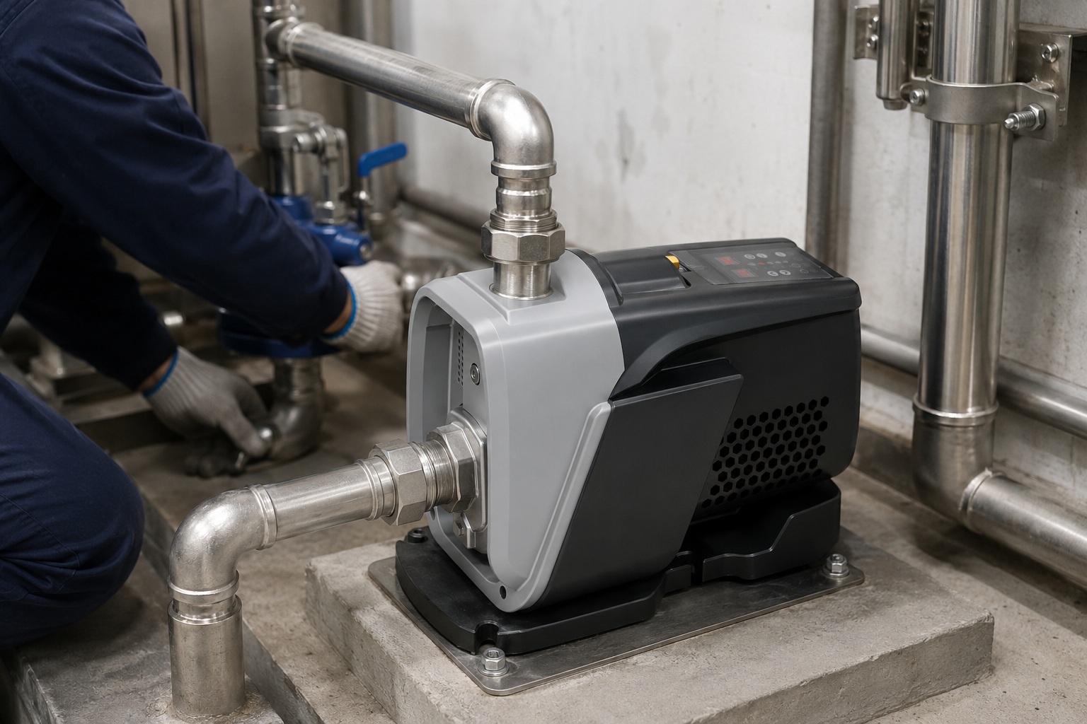
Excellence in Mechanical and Material Engineering
Failing to consider a motor's mechanical limits is a costly mistake.
The physical construction of a motor determines its durability and suitability for an application.
Learn what makes a motor robust.
The mechanical design of a DC series motor is not intended for the uncontrolled high-speed runaway condition created by a centrifugal pump's low starting load.
Recommended motors, like AC or DC shunt types, are built with materials and components engineered for stable, continuous-speed operation.
Beyond the electrical principles, the mechanical and material engineering of a motor plays a vital role.
A motor is a complex assembly of bearings, shafts, windings, and housing.
All of these parts must be designed to withstand the stresses of its intended application.
Choosing a motor involves matching not only its electrical characteristics but also its physical robustness to the task.
A motor built for high-torque, intermittent-duty cycles will have a different construction than one designed for continuous, high-efficiency operation.
Let's explore the key mechanical components that differentiate suitable motors from unsuitable ones for centrifugal pump duty.
The Role of Premium Bearings
High-quality bearings are critical for any motor.
Their importance is magnified in constant-speed applications like pumping.
They ensure the rotor spins with minimal friction, noise, and vibration.
Motors intended for continuous duty often feature high-precision bearings from reputable manufacturers.
These components offer quieter operation and a significantly longer lifespan compared to standard alternatives.
In the runaway scenario of a DC series motor, standard bearings would quickly overheat and fail due to excessive speed and vibration, leading to a complete mechanical seizure.
Stator and Rotor Design for Longevity
The stator and rotor are the heart of the motor.
Their design and materials directly impact efficiency and durability.
High-quality motors use specific materials to optimize performance.
- High-Grade Silicon Steel: This is used in the stator to enhance motor efficiency by reducing electrical core losses.
- High-Temperature Magnets/Windings: Rotors in premium motors, especially PMSM types, use advanced ferrite or rare-earth magnets that can withstand high temperatures without losing their magnetic properties. Stator windings use high-thermal-class wire (e.g., Class F) to operate reliably under heavy loads.
- Thermal Management: A low temperature rise indicates superior thermal management. Efficient cooling, whether through fan design or housing fins, is crucial for extending the motor's operational lifespan.
A DC series motor, when over-speeding, generates immense heat very quickly.
This can easily exceed the thermal limits of its insulation and windings, causing a short circuit and burnout.
Impeller and Housing Materials
While part of the pump, the impeller's material is chosen in synergy with the motor's capability.
Centrifugal pumps often use corrosion-resistant and durable materials like AISI 304 stainless steel or engineered composites for their impellers.
These materials are strong but have maximum rotational speed limits.
The uncontrolled speed of a DC series motor can exceed these limits, causing the impeller to deform or shatter.
This sends fragments through the plumbing system and destroys the pump.
The motor housing itself should also be durable, often made from cast iron or UV-resistant polymers for protection against harsh environments.
Uncompromising Electronic Reliability
Pump electronics often fail due to moisture.
An unsealed controller is a ticking time bomb.
Investing in properly protected electronics prevents costly premature failure and downtime.
The most reliable pump motors feature completely sealed main controller boards.
This is achieved through PCB potting, creating a waterproof and dustproof barrier that achieves a high IP rating and can extend the controller's lifespan by shielding it from environmental damage.
In the world of pumps, water is both the medium being moved and the greatest threat to the system's electronics.
Moisture, condensation, dust, and vibration can all lead to short circuits and corrosion on a printed circuit board (PCB).
This is a common point of failure.
While a simple DC series motor may have minimal electronics, any modern, efficient pump system relies on a sophisticated controller.
Protecting this electronic brain is paramount for long-term reliability.
A simple plastic cover is not enough.
The Gold Standard: Full PCB Potting
The most robust method for protecting electronics is full potting.
In this process, the entire PCB is encapsulated in a non-conductive, thermally conductive epoxy or silicone compound.
This creates a solid, impenetrable block that offers multiple layers of protection.
- Total Environmental Sealing: Potting creates a 100% waterproof and dustproof seal. This allows the electronics to achieve a high Ingress Protection (IP) rating, like IP67, meaning it can be submerged in water without damage. This completely prevents failures caused by moisture, humidity, and condensation.
- Vibration and Shock Resistance: The solid compound encasing the components prevents them from vibrating or being damaged by mechanical shocks, which are common in pump operations. Solder joints are protected from stress and cracking.
- Improved Thermal Dissipation: The potting compound helps to draw heat away from sensitive electronic components and transfer it to the motor's housing. This keeps the electronics running cooler and extends their life.
By isolating the sensitive electronics from the harsh operating environment typical for pumps, this feature is projected to extend the controller's lifespan significantly, often by several years.
Why Standard Enclosures Fail
Many lower-quality systems rely on simple enclosures or conformal coatings.
While a conformal coating (a thin protective film) offers some protection, it can be scratched and does not provide the same level of waterproofing or vibration damping.
Standard enclosures often have seals that can degrade over time, allowing moisture to creep in.
Changes in temperature can cause air inside an enclosure to expand and contract, drawing in moist air that then condenses on the cool PCB surfaces.
This is a slow but certain path to failure.
Investing in a system with fully potted electronics is a direct investment in the pump's long-term reliability and a significant reduction in lifetime maintenance costs.
It is a hallmark of high-quality engineering that separates premium products from those destined for early replacement.
A Comprehensive Suite of Protection Functions
A motor running without safeguards is an accident waiting to happen.
Faults like dry running or voltage spikes can destroy a pump in seconds.
A truly intelligent system actively protects itself.
Modern pump controllers feature a comprehensive suite of protection functions.
These systems actively monitor electrical and hydraulic conditions, automatically shutting down or adjusting operation to prevent damage from faults like dry running, overheating, voltage issues, freezing, and pipeline leaks.
A basic motor setup simply runs when power is applied and stops when it is cut.
It has no awareness of the conditions it is operating under.
This is a major liability, as many common issues in a water system can quickly destroy a pump or motor.
In contrast, an intelligent pump system is equipped with a sophisticated, microprocessor-controlled protection suite that acts as a vigilant guardian for the equipment.
These protections go far beyond a simple fuse or circuit breaker.
They offer proactive and intelligent responses to a wide range of potential faults.
Key Electrical and Thermal Protections
These functions safeguard the motor and its electronic driver from damaging electrical events.
- Input Voltage Protection: The system monitors incoming voltage. It will shut down if the voltage is too high or too low, protecting the electronics from burnout or malfunction.
- Overcurrent and Stall Protection: If the motor draws too much current, either from a jam (stall) or an internal fault, the system cuts power to prevent overheating and winding damage.
- Phase Loss Protection: In three-phase systems, the loss of one phase can quickly destroy a motor. The controller instantly detects this and shuts the unit down.
- Overheating Protection: Multiple sensors monitor the temperature of the driver board and the motor itself. If temperatures exceed safe limits, the system will shut down to cool off.
Critical System and Hydraulic Protections
These functions protect the pump from the hydraulic system it's connected to.
- Water Shortage (Dry Run) Protection: This is one of the most important protections. Running a pump without water causes the seals to overheat and fail rapidly. An intelligent system uses sensors to detect a lack of water. It will then stop the pump and may enter an intelligent recovery algorithm. For example, it might try to self-prime for a short period, then wait before trying again, conserving energy while periodically checking for water return. A simple DC series motor has no such awareness and would simply run until it burns out.
- Antifreeze Protection: In cold climates, a sensor can detect if the water temperature is nearing freezing. The controller can then briefly run the pump to circulate the water and prevent ice from forming and cracking the pump housing.
- Pipeline Leak Warning: By analyzing pressure and flow patterns, an advanced system can detect small, continuous flows that indicate a leak in the plumbing. It can then alert the user to the potential problem, saving water and preventing water damage.
These comprehensive protections are a defining feature of a high-quality, modern pump system.
They showcase the difference between a simple motor and a complete, intelligent pumping solution designed for reliability and a long service life.
Intuitive User Interface and Real-Time Monitoring
Complex systems are useless if they are difficult to control.
Users are often frustrated by confusing interfaces and a lack of real-time data.
A great system should be powerful yet simple to operate.
Top-tier pump controllers balance advanced functionality with an intuitive user interface.
They provide simple controls for everyday operation, like pressure adjustments, alongside access to deep real-time data for diagnostics, giving users both ease of use and powerful insight into their system's performance.
Even the most technologically advanced pump is of little value if the end-user cannot easily operate it or understand what it's doing.
The days of cryptic dip switches and confusing manuals are over.
Modern engineering emphasizes user-centric design, providing clear controls and transparent access to operational data.
This approach empowers users to set up their system correctly and allows technicians to diagnose issues quickly.
A simple DC series motor offers no feedback.
An intelligent pump system, however, provides a window into its own operation.
Simple Controls for Daily Use
Despite the complexity under the hood, daily operation should be straightforward.
A well-designed interface achieves this through a few key elements.
- Clear Buttons: Simple, clearly labeled buttons for essential functions like On/Off and pressure adjustments (Up/Down) make the system accessible to anyone.
- At-a-Glance Indicators: A series of distinct LED indicators provides immediate visual feedback on the system's status. A quick glance can confirm if the pump is running, if it's in constant pressure mode, or if a fault like a water shortage has occurred.
An effective interface may also include one-touch functions for common tasks.
For example, a long press of a button might initiate a factory reset or cycle through different display modes, keeping the main interface uncluttered.
Deep Insight Through Live Data Display
For installers, technicians, or curious homeowners, access to real-time data is invaluable for diagnostics and performance optimization.
Advanced controllers often include a digital display that can cycle through a wealth of live operating parameters.
This turns the pump into its own diagnostic tool.
Example of Real-Time Data:
| Display Code | Parameter | What It Tells You |
|---|---|---|
| P.xxx | Real-Time Power (Watts) | Shows how much energy the pump is currently using. |
| xxxx | Motor Speed (RPM) | Confirms how the VFD is adjusting motor speed to meet demand. |
| U.xxx | Input Voltage (Volts) | Helps diagnose power supply issues without a multimeter. |
| A.xx | Water Temperature | Useful for monitoring hot water systems or high-temp conditions. |
| t.xx | PCB Temperature | Provides an early warning of potential electronic overheating issues. |
This level of transparency is a hallmark of a high-quality, engineered product.
It shows confidence in the design and provides users with the tools they need to ensure the system is running optimally.
Optional features like WiFi connectivity can take this a step further, allowing for remote monitoring and adjustments via a smartphone app.
Conclusion
Never use a DC series motor for centrifugal pumps due to its dangerous no-load over-speed risk.
Instead, choose stable, constant-speed motors like DC shunt or standard AC induction motors.
FAQs
What type of motor is used in a centrifugal pump?
Centrifugal pumps most commonly use three-phase AC induction motors for industrial use. For smaller or DC systems, DC shunt motors are used due to their constant speed characteristics.
Why is starting torque of a centrifugal pump low?
The starting torque is low because the pump's impeller is not yet moving a significant volume of fluid. The resistance only increases as the fluid begins to flow.
Can a single-phase motor be used for a centrifugal pump?
Yes, single-phase AC motors are often used for smaller residential centrifugal pumps. However, they are less efficient and less powerful than their three-phase counterparts for larger applications.
What is the difference between a series and shunt motor?
In a series motor, the field winding is in series with the armature, causing speed to vary with load. In a shunt motor, they are in parallel, providing constant speed.
Which motor has the highest starting torque?
The DC series motor has the highest starting torque among common DC motors, which is why it's used for applications like cranes and elevators, but not constant-speed pumps.
What happens if you run a centrifugal pump with no load?
Running a centrifugal pump with no load (no water) will cause it to overheat and fail quickly. If powered by a DC series motor, it will also dangerously over-speed.
Which motor should I use for a pump?
For most pump applications, a standard AC induction motor is the best choice. If precise speed control is needed for constant pressure, use an AC motor with a VFD controller.
Can a VFD be used with any motor?
No, a VFD is designed to be used with AC induction or permanent magnet synchronous motors. It cannot be used to control DC motors like series or shunt types.