Struggling to get water where you need it?
A pump without enough lift can cause system failure.
This leads to costly downtime and project delays.
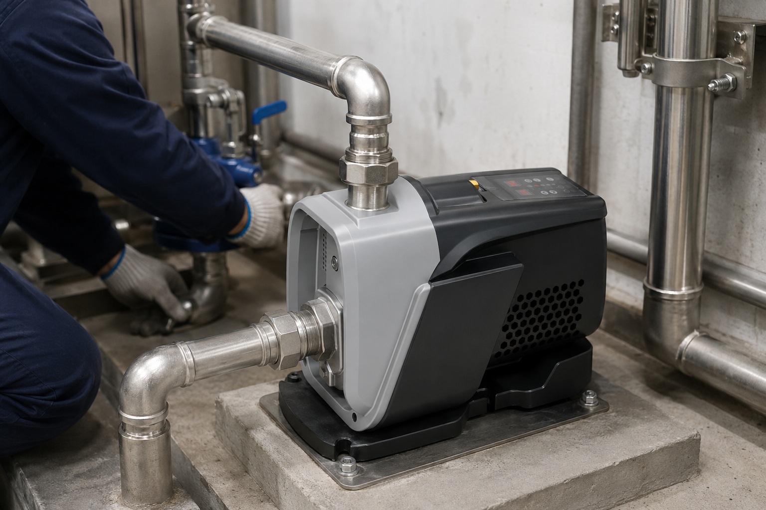
A centrifugal pump's lifting distance, or "head," is not one single number. It depends on the pump’s design, motor power, and the specific piping system it's installed in. Small domestic pumps might lift water 20-40 meters, while large multi-stage industrial models can push water well over 150 meters.
Now you have a general idea of the lifting range.
But the real answer lies in the details of your specific aplication.
Understanding these details is the key to selecting a pump that performs reliably and efficiently.
Let's break down the factors that truly define a pump's lifting power.
This knowledge will empower you to choose the perfect pump every time.
Understanding the Core Concept: What Exactly is "Head"?
Confused by pump jargon like "head"?
Misunderstanding this term leads to selecting the wrong pump.
This results in poor performance and wasted energy.
"Head" is the height to which a pump can raise a column of fluid. It is a measure of the energy the pump imparts to the fluid, expressed as a height (e.g., in meters or feet). It is the most critical factor in determining a pump's vertical lifting capability.
The term "head" seems simple.
But it's actually a combination of several different forces and factors.
To make the right choice for your business, you need to understand how these components work together.
It is not just about the vertical distance from the pump to the outlet.
It also includes overcoming resistance within the entire system.
A deeper understanding of head ensures you are not just buying a pump.
You are investing in a solution that is perfectly matched to your operational needs, preventing both underperformance and excessive energy consumption. Overlooking this can lead to a pump that either fails to deliver the required flow or operates inefficiently, increasing costs by up to 20-30%.
Breaking Down Total Dynamic Head (TDH)
Total Dynamic Head (TDH) is the total equivalent height that a fluid is to be pumped, taking into account all losses in the system.
It is the true workload placed on the pump.
We can break it down into four main components.
- Static Lift Head: This is the most straightforward part. It is the simple vertical distance you need to lift the water. It is measured from the surface of the water source to the highest point of the aplication.
- Static Suction Head: This is the vertical distance from the centerline of the pump down to the surface of the liquid source. This is a critical factor, especially when the pump is located above the water source.
- Pressure Head: If the pump is discharging into a pressurized tank, this pressure must be converted into an equivalent height of water. This "pressure head" must be added to the total head calculation. For example, 1 bar of pressure is equivalent to approximately 10.2 meters of head.
- Friction Head (or Friction Loss): This is the "hidden" energy consumer. As water flows through pipes, fittings, and valves, it creates friction. This friction acts as a resistance that the pump must overcome. This resistance is the friction head.
Calculating TDH: A Practical Look
Understanding these components is one thing.
Calculating them is another.
The formula looks like this:
TDH = Static Lift Head + Pressure Head + Friction Head
| Component | Description | Example Factor |
|---|---|---|
| Static Lift Head | The total vertical elevation change. | 20 meters |
| Pressure Head | Required pressure at the outlet. | 1.5 Bar (≈ 15.3m Head) |
| Friction Head | Losses from pipes, valves, and bends. | Can add 10-30% to TDH |
Friction head is the most complex to calculate.
It depends on the flow rate, pipe diameter, pipe length, and the number and type of fittings.
A larger pipe diameter significantly reduces friction loss.
For example, doubling the pipe diameter can reduce friction loss by a factor of 16 for the same flow rate.
Failing to accurately account for friction is a common reason for underperforming pump systems.
Key Factors That Determine Lifting Height
Worried your pump won't meet the height requirements?
Choosing based on motor power alone is a common mistake.
This often leads to a system that fails under real-world conditions.
A pump's maximum lift is determined by its specific pump performance curve, not just its horsepower. Factors like impeller diameter, motor speed (RPM), and the pump's design efficiency directly dictate the achievable head and flow rate for any given application.
You know that "head" is the goal.
Now, let's look at the tools you have to achieve it.
The lifting capacity of a centrifugal pump is not a single, fixed number.
It's a dynamic variable influenced by a precise set of engineering and environmental factors.
Understanding these factors is crucial for anyone involved in specifying, purchasing, or installing pump systems.
Getting it right means a reliable, long-lasting installation.
Getting it wrong means callbacks, warranty claims, and unhappy customers.
The Pump Performance Curve is Your Guide
The single most important document for any pump is its performance curve.
This graph is the pump's resume.
It tells you exactly how the pump will perform under different conditions.
The curve plots the relationship between the flow rate (usually on the x-axis) and the head (on the y-axis).
- Shut-off Head: This is the point of zero flow on the curve. It represents the maximum head the pump can generate. At this point, the pump is running, but the discharge valve is closed, so no water is moving.
- Best Efficiency Point (BEP): This is the point on the curve where the pump operates most efficiently, converting the highest percentage of motor energy into water energy. Operating a pump near its BEP ensures lower energy costs and a longer operational life. Running a pump too far from its BEP (more than 25% away) can lead to increased vibration, cavitation, and premature failure of bearings and seals.
- Relationship: As you demand more flow from the pump (moving right on the curve), the amount of head it can produce decreases.
Critical Pump and System Characteristics
Beyond the curve itself, several design and system elements play a major role.
It's a mistake to look at the pump in isolation.
The pump and the system it's in work together as a single unit.
| Factor | Impact on Lifting Height | Key Consideration |
|---|---|---|
| Impeller Diameter | Larger diameter generally produces more head. | A 10% increase in impeller diameter can result in a ~21% increase in head. |
| Motor Speed (RPM) | Higher speed increases both flow and head. | Doubling the speed can quadruple the head (Head ∝ RPM²). |
| Number of Stages | Multi-stage pumps use multiple impellers in series. | Each stage adds to the total head, allowing for very high lifts. |
| Fluid Properties | Higher density or viscosity requires more energy. | Pumping a fluid 1.2x denser than water requires 1.2x more power for the same head. |
The choice between a high-speed single-stage pump and a lower-speed multi-stage pump is a key engineering decision.
Multi-stage pumps are often chosen for high-head, low-flow applications like boiler feed or high-rise building water supply because they can achieve massive pressures more efficiently than a single, oversized impeller.
Understanding these variables allows you to fine-tune your selection process for maximum performance and cost-effectiveness.
The Difference Between Suction Lift and Total Head
Is your pump struggling to even pull water in?
You might be confusing suction capability with total discharge power.
These two very different limits can make or break your installation.
Suction lift is the vertical distance a pump can pull water from a source below it, limited by atmospheric pressure to about 7-8 meters in practice. Total head is the total height it can push water, determined by the pump's power and design.
Many people use the term "lift" interchangeably.
But in pump engineering, "lift" has two very distinct meanings.
Failing to differentiate between them is one of the most common and costly mistakes in system design.
One is about pulling water into the pump.
The other is about pushing it out.
They are governed by entirely different physical principles and have vastly different limitations. Let's clarify this crucial distinction to ensure your systems are designed for success from the ground up.
Understanding Suction Lift: The Pulling Limit
A centrifugal pump does not "suck" water in the traditional sense.
It works by creating a low-pressure zone at the eye of the impeller.
Atmospheric pressure, pressing down on the surface of the water source, then pushes the water up the suction pipe and into the pump.
This means suction lift has a hard physical limit.
- Theoretical Limit: At sea level, a perfect vacuum can theoretically lift a column of water about 10.3 meters.
- Practical Limit: In the real world, you can never achieve a perfect vacuum. Friction in the suction pipe and the vapor pressure of the water reduce this significantly. A safe and realistic maximum suction lift for a standard centrifugal pump is around 7 meters (about 23 feet). For every 1000 meters of altitude increase, this practical limit decreases by approximately 1 meter due to lower atmospheric pressure.
The Danger of Exceeding Suction Lift: NPSH and Cavitation
When you try to pull water from too far below, or if the suction line has too much friction, the pressure inside the pump can drop below the water's vapor pressure.
This causes the water to spontaneously boil, even at room temperature.
This phenomenon creates tiny vapor bubbles that collapse violently as they move toward the higher-pressure areas of the impeller. This is called cavitation.
Effects of Cavitation:
- Severe Damage: The collapse of bubbles creates micro-jets of water that can erode the impeller, causing pitting and damage that looks like it's been sand-blasted.
- Noise and Vibration: A pump experiencing cavitation will sound like it's pumping gravel and will vibrate excessively, leading to bearing and seal failure.
- Performance Drop: Cavitation disrupts the flow through the pump, causing a dramatic drop in both head and flow rate.
To avoid this, we use a metric called Net Positive Suction Head (NPSH). There is NPSH Available (NPSHa) from the system, and NPSH Required (NPSHr) by the pump. You must always ensure NPSHa > NPSHr. A safety margin of at least 0.5 to 1 meter is highly recommended.
Total Head: The Pushing Power
Once the water is successfully inside the pump, total head takes over.
This is the "pushing" side of the equation.
Unlike suction lift, total head is not limited by atmospheric pressure.
It is limited only by the energy the pump can add to the water.
This is determined by the factors we've already discussed: motor power, impeller design, and RPM.
This is why a small pump might have a total head of 30 meters, while a large industrial multi-stage pump can achieve heads of 500 meters or more, all while having the same suction lift limit of around 7 meters.
How to Calculate the Required Head for Your System
Are you just guessing your system's head requirements?
A rough estimate can lead to buying an oversized or undersized pump.
This results in high energy bills or a system that simply doesn't work.
To calculate required head, you must sum the static vertical lift, all friction losses from pipes and fittings, and any required outlet pressure. This total, known as Total Dynamic Head (TDH), is the true performance target your pump must meet.
Theory is good, but practical application is what matters.
As a business owner, you need a reliable method to determine the exact requirements for your projects.
Calculating the Total Dynamic Head (TDH) is not an academic exercise.
It is a critical step in the procurement process.
This calculation ensures you select a pump that delivers the performance you need without wasting money on an oversized unit or risking failure with one that is too small.
A pump oversized by just 10% can increase energy consumption by over 20%.
Let's walk through a structured, step-by-step process.
Step-by-Step Guide to Calculating TDH
Follow these four steps for an accurate calculation.
You will need some basic information about your system layout.
It's best to draw a simple diagram of your piping system first.
Step 1: Determine the Total Static Head
This is the easiest part.
It's the pure vertical distance the water needs to travel, independent of any flow.
- Measure the vertical distance from the surface of the water source (e.g., a tank or well) to the centerline of the pump. This is the Static Suction Lift.
- Measure the vertical distance from the pump's centerline to the final discharge point. This is the Static Discharge Head.
- Total Static Head = Static Suction Lift + Static Discharge Head.
Step 2: Determine the Required Pressure Head
Does your system discharge into open air, or into a pressurized environment?
If you are just filling a tank at atmospheric pressure, your Pressure Head is zero.
However, if you are feeding a boiler, a closed-loop system, or a sprinkler system, you need to account for this.
- Take the required pressure at the outlet in Bar or PSI.
- Convert this pressure to head. A useful conversion is 1 Bar ≈ 10.2 meters of head.
- Pressure Head = Required Outlet Pressure (in Bar) x 10.2.
Step 3: Calculate the Friction Head
This is the most complex but most critical step.
Friction head is the energy lost due to friction as water moves through the pipes and fittings.
You will need a friction loss chart or an online calculator for this.
- Pipe Friction Loss: Determine the total length of your pipe. Using a chart, find the friction loss in "meters of head per 100 meters of pipe" for your pipe's diameter and the desired flow rate. Calculate the total loss for your pipe length.
- Fitting Friction Loss: Every elbow, valve, and tee adds friction. These are typically expressed as an "equivalent length" of straight pipe. Add this equivalent length to your total pipe length before calculating friction loss. For instance, a 90° elbow might be equivalent to 2 meters of straight pipe.
Step 4: Sum It All Up
Now, you just add the components together.
Total Dynamic Head (TDH) = Total Static Head + Pressure Head + Total Friction Head
This final TDH value, along with your desired flow rate, gives you the exact duty point your pump needs to meet.
Choosing the Right Centrifugal Pump for Your Desired Lift
Do you pick pumps based on a catalogue's maximum head value?
This number is often the "shut-off head" with zero flow.
Choosing a pump this way guarantees it will underperform in a real system.
Select a pump whose Best Efficiency Point (BEP) is as close as possible to your system's required duty point (the intersection of your required flow and Total Dynamic Head). This ensures optimal performance, energy efficiency, and maximum operational lifespan.
You have done the hard work.
You have calculated your required flow rate and your Total Dynamic Head.
You now have a specific performance target: your "duty point."
The final step is to match this duty point to the right pump.
This is where you translate your system's needs into a product selection.
This is a decision that directly impacts long-term operational costs and system reliability.
Choosing correctly is the hallmark of a professional installation.
From Duty Point to Pump Curve
Your duty point is a single point on a graph: Flow Rate on the X-axis and TDH on the Y-axis.
Your goal is to find a pump whose performance curve intersects with or is very close to this point.
But there's one more crucial element: the Best Efficiency Point (BEP).
- Identify the Duty Point: Plot your calculated TDH and desired flow rate.
- Review Pump Curves: Look at manufacturer-provided pump curves. Find models where your duty point falls on the curve.
- Prioritize the BEP: Among the potential candidates, choose the pump where your duty point is closest to the BEP. Operating within a range of 80% to 110% of the BEP flow rate is considered good practice.
The Dangers of Sizing Incorrectly
It can be tempting to add a "safety factor" and choose a much larger pump.
This is often a costly mistake.
Both oversizing and undersizing have significant negative consequences.
| Sizing Error | Consequence | Financial Impact |
|---|---|---|
| Undersizing | The pump cannot meet the required head or flow. | System failure. Inability to deliver water, requiring immediate replacement. |
| Oversizing | The pump operates far to the left of its BEP. | High energy consumption, excessive vibration, leading to cavitation, and premature seal and bearing failure. Running a pump 20% oversized can increase lifetime energy costs by 40% or more. |
Considering Variable Speed Drives (VSD)
For systems where the required head or flow varies, a Variable Speed Drive (VSD) pump is an excellent investment.
A VSD allows you to adjust the motor's RPM.
Based on the Affinity Laws, even a small reduction in speed can lead to significant energy savings.
- Flow is directly proportional to speed (RPM).
- Head is proportional to the square of the speed (RPM²).
- Power is proportional to the cube of the speed (RPM³).
This means that reducing the pump speed by just 20% can result in energy savings of nearly 50%.
For a customer like Andrew in Australia, where energy costs are high, specifying a VSD pump can be a major competitive advantage, offering a rapid return on investment and demonstrating a commitment to quality and long-term value.
Optimizing Your System to Maximize Lift and Efficiency
Is your pump system underperforming despite being sized correctly?
The problem might not be the pump itself.
Often, inefficiencies in the piping system are robbing your pump of its power.
To maximize lift and efficiency, use larger diameter piping to reduce friction loss, minimize the number of bends and fittings, and ensure all connections are airtight. A well-designed system can improve pump performance by over 15% without changing the pump itself.
You have chosen the perfect pump for the job.
But the process doesn't end there.
The efficiency and performance of your entire system depend heavily on the design of the suction and discharge piping.
A powerful pump connected to a poorly designed pipe system is like a sports car stuck in a traffic jam.
It has the potential for high performance, but the surrounding conditions are holding it back.
By optimizing the system, you ensure that the energy you are paying for is used to move water, not just to overcome unnecessary friction.
This focus on total system efficiency is what separates a standard installation from a high-performance one.
The Golden Rules of Efficient Piping
Small changes in piping design can lead to major improvements in performance and significant reductions in energy costs.
Follow these best practices to get the most out of every pump you install.
1. Go Bigger on Pipe Diameter
This is the single most effective way to reduce friction head.
While larger pipes have a higher initial cost, the lifetime energy savings are almost always worth it.
- The Rule of Thumb: Increasing the pipe size by one nominal diameter can often reduce friction loss by 40-60% for a given flow rate.
- Suction Side: It is especially critical to have a large-diameter suction pipe. A common best practice is to have the suction pipe be one size larger than the pump's suction nozzle.
2. Keep it Straight and Simple
Every bend, elbow, and valve adds to the friction loss.
A streamlined path is an efficient path.
- Minimize Bends: Use gentle, sweeping bends (long-radius elbows) instead of sharp 90-degree elbows where possible. A single 90° elbow can add as much friction as several meters of straight pipe.
- Valve Selection: Use full-port ball valves or gate valves that offer minimal restriction when fully open. Avoid using globe valves for throttling flow; use a VSD instead.
Maintenance for Sustained Performance
An optimized system needs to stay optimized.
Regular maintenance is key to preventing performance degradation over time.
| Maintenance Task | Frequency | Impact of Neglect |
|---|---|---|
| Check for Suction Leaks | Monthly | Air entering the suction line can cause the pump to lose prime and lead to cavitation. |
| Inspect Foot Valve/Strainer | Quarterly | A clogged strainer restricts flow, dramatically increasing suction head and starving the pump. |
| Monitor Pressure Gauges | Daily/Weekly | A change in pressure readings is often the first sign of a problem, like a clog or a leak. |
| Check for Vibration/Noise | During Operation | An increase in noise or vibration can indicate bearing wear or developing cavitation. |
By building efficient systems from the start and maintaining them properly, you ensure that the pump's lifting capability is not wasted.
This approach delivers maximum value to the end-user and solidifies your reputation as a quality-focused supplier.
Conclusion
A pump's lifting distance, or head, is a function of its design and the system it serves.
Understanding static lift, pressure, and friction is key.
Matching your system's total head to the pump's efficiency curve ensures optimal, reliable performance.
Frequently Asked Questions
What is the maximum suction lift for a centrifugal pump?
The theoretical maximum is 10.3 meters. However, in practice, a safe suction lift is around 7-8 meters at sea level due to friction and other factors.
Can a centrifugal pump run without water?
No, running a centrifugal pump dry will rapidly damage the mechanical seal and bearings due to lack of lubrication and cooling, leading to quick failure.
How do I increase the pressure of my centrifugal pump?
You can increase pressure (head) by increasing the motor speed with a VSD, replacing the impeller with a larger one, or using a multi-stage pump.
What is the difference between head and pressure?
Head is the height a pump can lift a fluid, measured in meters. Pressure is the force exerted by that fluid, measured in Bar or PSI.
Why is my pump not building pressure?
This could be due to running in reverse, a suction leak, a clogged strainer, a damaged impeller, or the pump being air-locked (not primed).
How does viscosity affect pump performance?
Higher viscosity fluids create more friction, which reduces the pump's achievable head and flow rate. It also requires more motor power to operate.
What happens if you oversize a centrifugal pump?
Oversizing causes the pump to run inefficiently, consuming excess energy. It also leads to increased vibration, noise, and potential damage from running too far from its BEP.
Can I use a smaller pipe on the pump discharge?
While possible, using a smaller discharge pipe increases friction loss. This forces the pump to work harder, reducing the overall flow rate and efficiency of the system.