Struggling with inconsistent water pressure?
This problem can disrupt daily routines and damage appliances.
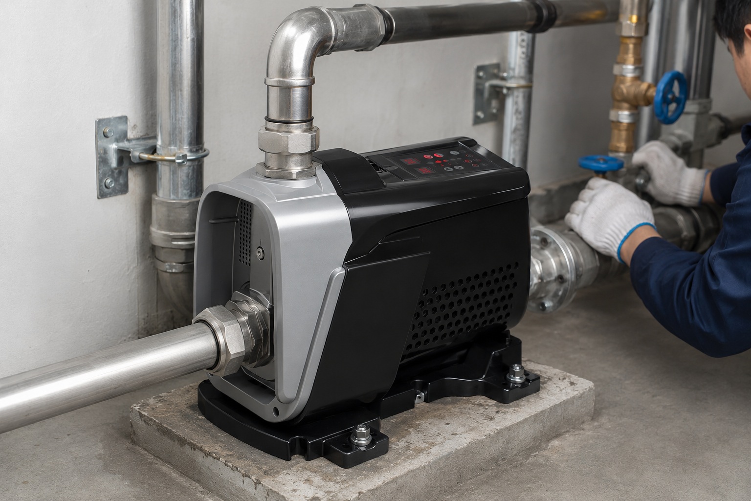
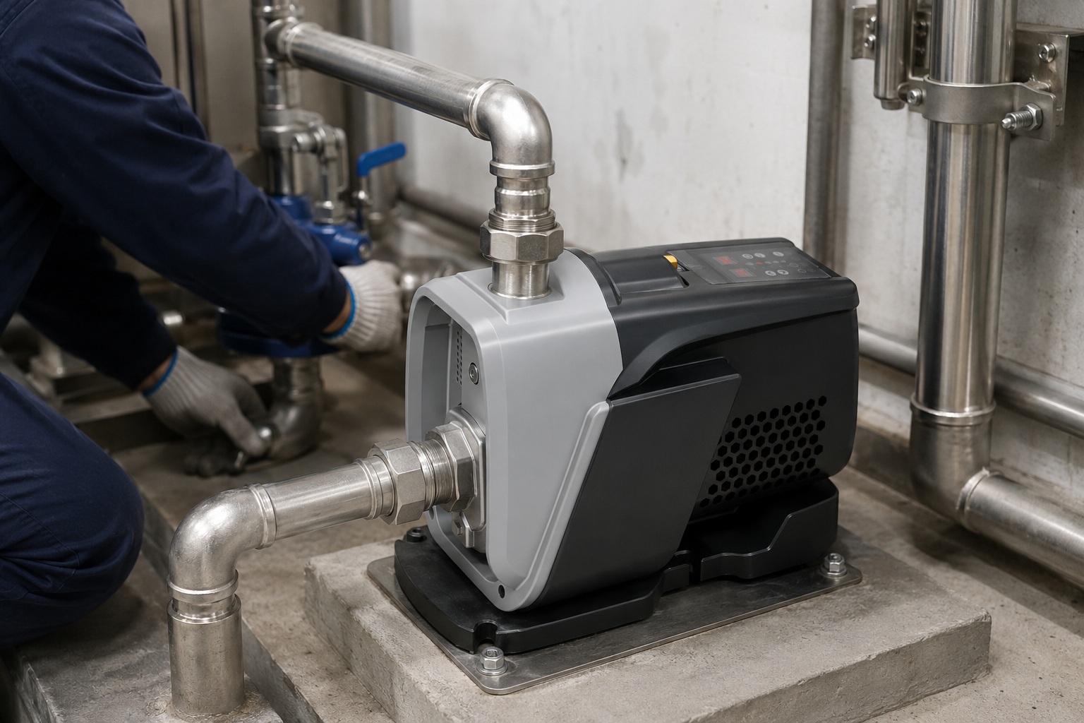
An electric water pump provides the reliable flow you need by converting electrical energy into hydraulic energy.
An electric water pump operates using a motor and an impeller. The motor spins the impeller at high speed. This rotation creates a low-pressure zone at the center, drawing water in. Centrifugal force then pushes the water outwards at high velocity into the pump's casing, increasing its pressure before it is discharged.
This simple-sounding process involves a precise interplay of several key components and physical principles.
Understanding this mechanism is crucial for selecting the right pump for your business and ensuring its long-term performance.
Let's explore the essential parts that make this technology possible and how they work together to move water efficiently.
The Core Components of an Electric Water Pump
Confused by the technical jargon of pump parts?
This confusion can make it difficult to assess pump quality and maintenance needs.
Knowing the core components helps you make informed purchasing and service decisions.
Every electric water pump consists of a motor that provides power, an impeller that moves the water, and a casing (volute) that directs the flow. These three main parts work together to create pressure and move water from the inlet to the outlet.
Each component plays a distinct and vital role.
The motor is the engine, the impeller is the heart, and the casing is the circulatory system.
A failure in any one of these parts can lead to a significant drop in performance or complete system failure.
The quality of materials and engineering precision of these components directly impacts the pump's efficiency, durability, and overall lifespan.
For importers and distributors, recognizing high-quality components is key to providing reliable products to your customers.
Let's break down each of these critical parts to understand their function and importance more deeply.
H3: The Electric Motor: The Powerhouse
The electric motor is the prime mover of the pump.
It converts electrical energy into the mechanical rotational energy needed to drive the pump.
The motor consists of a a stator and a rotor.
The stator is the stationary part, containing coils of wire.
When electricity passes through these coils, it creates a rotating magnetic field.
This magnetic field interacts with the rotor, the rotating part of the motor, causing it to spin.
The rotor is connected to the pump shaft.
The shaft then transfers this rotational motion directly to the impeller.
Motors are rated by power (in kilowatts or horsepower), voltage, and phase (single-phase or three-phase).
The efficiency of a motor is a critical factor, often exceeding 90% in modern designs like permanent magnet synchronous motors (PMSM).
A higher efficiency motor consumes less electricity to produce the same amount of work, leading to lower operating costs over the pump's lifetime.
H3: The Impeller: The Heart of the Pump
The impeller is the rotating component that imparts velocity to the water.
It is the true heart of the pump's hydraulic end.
It has a series of curved vanes.
As the impeller spins, these vanes catch the water entering at the center (the "eye").
The rotation flings the water outward toward the edge of the impeller using centrifugal force.
This action dramatically increases the water's velocity.
Impellers come in several designs:
- Open Impellers: Vanes are attached to a central hub without any sidewalls. They are good for handling solids but are less efficient.
- Semi-Open Impellers: Vanes have one sidewall (a backplate), providing more efficiency than open designs while still handling some small solids.
- Closed Impellers: Vanes are enclosed between two sidewalls (a front and back shroud). This is the most efficient design, used for clear liquids, as it minimizes recirculation and maximizes pressure development. Over 85% of clean water booster pumps use closed impellers.
The material of the impeller, such as cast iron, bronze, or stainless steel, is chosen based on the liquid being pumped and the need for corrosion or abrasion resistance.
H3: The Casing (Volute): The Guiding Path
The casing, often called the volute, is the stationary housing that encloses the impeller.
Its primary role is to collect the high-velocity water from the impeller and convert that velocity into pressure.
The volute has a cleverly designed shape.
It is a spiral-shaped funnel with a cross-sectional area that gradually increases toward the discharge outlet.
As the water is flung from the impeller's edge into the volute, it slows down because the area increases.
According to Bernoulli's principle, as the fluid's velocity decreases, its pressure must increase.
This conversion process is the key to how a centrifugal pump builds discharge pressure.
A well-designed volute can increase the pump's overall efficiency by 5-10% by minimizing energy losses during this velocity-to-pressure conversion.
Table: Component Function and Importance
| Component | Primary Function | Importance for Performance |
|---|---|---|
| Motor | Converts electrical energy to mechanical rotation. | Determines power, speed, and energy efficiency. A high-efficiency motor reduces operating costs. |
| Impeller | Transfers mechanical energy to the water as velocity. | Directly creates water flow. Design (open, closed) and material dictate efficiency and application. |
| Casing (Volute) | Converts the water's high velocity into high pressure. | Crucial for pressure generation. Its design significantly impacts the pump's overall efficiency. |
| Shaft | Connects the motor to the impeller. | Must be strong and precisely aligned to prevent vibration and premature wear on bearings and seals. |
| Mechanical Seal | Prevents water from leaking out along the shaft. | Protects the motor from water damage. A critical component for pump longevity and reliability. |
The Pumping Mechanism: From Electricity to Water Flow
Is the step-by-step process of how a pump works unclear?
This lack of clarity can make troubleshooting performance issues a guessing game.
Understanding the sequence helps diagnose problems accurately.
The pumping mechanism starts when electricity powers the motor, spinning the impeller. This rotation creates a vacuum, drawing water in. The impeller then accelerates the water, and the casing converts this speed into high pressure, forcing the water out the discharge pipe.
This entire sequence, from power-on to pressurized water flow, happens almost instantaneously.
It's a beautiful conversion of energy from one form to another, guided by fundamental laws of physics.
Each step is a link in a chain, and the efficiency of the entire system depends on how well each link performs its job.
For anyone working with pumping systems, grasping this flow of energy and action is fundamental.
It transforms the pump from a black box into a logical system.
Let's trace this path in more detail to see exactly how electrical current becomes a powerful stream of water.
H3: Step 1: Electrical Energy Conversion
The process begins the moment you flip a switch.
Electrical current flows from the power source to the pump's motor.
Inside the motor, the stator's copper windings create a powerful, rotating magnetic field.
This field induces a current in the rotor, generating an opposing magnetic field.
The interaction between these two fields creates torque, forcing the rotor and the connected pump shaft to spin at high speed.
Modern variable frequency drive (VFD) pumps add a layer of intelligence here.
A VFD controller precisely manages the frequency and voltage of the electricity supplied to the motor.
By adjusting the frequency, the VFD can control the motor's speed with an accuracy of over 99%.
This allows the pump to match its output directly to the system's demand, saving up to 60% in energy consumption compared to fixed-speed pumps.
H3: Step 2: Creating a Pressure Differential
As the impeller begins to spin with the shaft, it starts to move the fluid already inside the pump casing.
This initial movement expels fluid from the impeller vanes out into the volute.
This action creates a zone of lower pressure at the very center of the impeller, known as the "eye."
Simultaneously, the pressure in the suction pipe connected to the pump inlet is higher (due to atmospheric pressure or the pressure from the water source).
Fluids naturally move from an area of higher pressure to an area of lower pressure.
This pressure differential is the force that "sucks" water from the source into the pump's inlet and toward the eye of the impeller.
The pump does not actually pull the water; it creates a low-pressure condition that allows the higher external pressure to push the water in. This is a critical distinction for understanding priming and suction lift limitations.
H3: Step 3: Centrifugal Force in Action
Once water enters the impeller's eye, it is captured by the spinning vanes.
Here, the core principle of centrifugal force takes over.
As the impeller rotates at high speeds, typically from 1,500 to 3,600 revolutions per minute (RPM), it subjects the water to a strong outward force.
This force accelerates the water particles radially, flinging them from the eye toward the outer edge of the impeller.
The energy transferred to the water at this stage is primarily kinetic energy, or the energy of motion.
The velocity of the water can increase by a factor of 10 or more as it travels through the impeller's vanes.
The final velocity of the water at the impeller tip is directly proportional to the impeller's diameter and its rotational speed.
A larger diameter or a faster spin results in higher water velocity and, consequently, a higher potential pressure.
H3: Step 4: Discharging the Water
The high-velocity water exits the impeller and enters the stationary casing, or volute.
The volute is designed to manage this energy transformation effectively.
Its gradually expanding spiral shape forces the water to slow down.
As the water's velocity decreases, its kinetic energy is converted into potential energy in the form of pressure.
This is the final and most important step in pressure generation.
By the time the water reaches the pump's discharge nozzle, its pressure has been significantly increased.
This new, higher pressure is what enables the water to overcome resistance in the piping system, travel to higher elevations, and exit a faucet or sprinkler with force.
The entire cycle is continuous as long as the pump is running, with new water constantly being drawn in as pressurized water is discharged.
Types of Electric Water Pumps and Their Principles
Overwhelmed by the different types of water pumps available?
Choosing the wrong type leads to inefficiency, poor performance, and premature failure.
Matching the pump type to the application is crucial for success.
The two main categories are centrifugal pumps, which use a rotating impeller and are best for high flow rates, and positive displacement pumps, which trap and force a fixed amount of water, excelling at high-pressure or high-viscosity applications.
While centrifugal pumps dominate the water-moving industry due to their simplicity and efficiency with low-viscosity fluids like water, positive displacement pumps have critical niches.
Understanding the fundamental difference in their operating principles is the first step toward selecting the right technology for a specific job.
One uses velocity and conversion; the other uses mechanical displacement.
This core difference affects everything from their performance curves to their maintenance requirements.
For distributors, offering a well-curated selection of both types can address a wider range of customer needs, from residential boosting to industrial processing.
Let's examine these categories and their common sub-types to build a clearer picture.
H3: Centrifugal Pumps: The Workhorses
Centrifugal pumps are the most common type, accounting for over 75% of pump installations worldwide.
Their operation, as we've discussed, relies on an impeller spinning to create flow.
They are ideal for moving large volumes of water at moderate pressures.
Their performance is described by a pump curve, which shows that as flow rate increases, the discharge pressure (head) decreases.
Key sub-types include:
- Surface Pumps: These pumps are installed on dry land, pulling water from a source. They are common for residential boosting, irrigation, and water transfer. Their suction lift is limited by atmospheric pressure, typically to about 7-8 meters.
- Submersible Pumps: The entire pump unit, including the sealed motor, is submerged in the fluid. This design eliminates the need for priming and is highly efficient because it pushes water instead of pulling it. They are widely used in deep wells, boreholes, and sumps.
- Vertical Multistage Pumps: These pumps use multiple impellers stacked in series on a single shaft. Each stage adds more pressure to the water. They are perfect for applications requiring very high pressure with a moderate flow rate, such as in high-rise buildings or reverse osmosis systems.
H3: Positive Displacement (PD) Pumps: The Specialists
Positive displacement pumps work by a completely different principle.
They trap a fixed volume of fluid in a chamber and then mechanically force it out the discharge pipe.
This creates a pulsating, non-continuous flow.
Unlike centrifugal pumps, a PD pump will produce the same flow rate regardless of the discharge pressure (head).
This makes them ideal for high-pressure, low-flow applications.
They are also excellent at handling viscous fluids or applications requiring precise dosing.
Common types include:
- Reciprocating Pumps: A piston, plunger, or diaphragm moves back and forth to displace the fluid. Piston pumps are classic examples used in high-pressure cleaning.
- Rotary Pumps: These use rotating elements like gears, lobes, or screws to move the fluid. Gear pumps are often used for oil and other viscous liquids.
H3: Choosing the Right Principle
The decision between centrifugal and positive displacement is the most fundamental choice in pump selection.
It is driven entirely by the application's requirements.
A centrifugal pump is the right choice for moving water for irrigation, general boosting, or circulation.
It offers high efficiency, simple construction, and lower maintenance costs.
However, if you need to pump a thick slurry, inject a precise chemical dose, or overcome extremely high system pressure, a positive displacement pump is necessary.
Attempting to use a centrifugal pump in a high-viscosity application would result in extremely low flow and potential motor overload.
Conversely, using a PD pump for simple water transfer would be inefficient and unnecessarily expensive.
Table: Centrifugal vs. Positive Displacement Pumps
| Feature | Centrifugal Pumps | Positive Displacement Pumps |
|---|---|---|
| Operating Principle | Converts velocity to pressure via an impeller. | Traps and mechanically displaces a fixed volume of fluid. |
| Flow Rate | Variable; decreases as pressure increases. | Constant; largely independent of pressure. |
| Pressure Handling | Best for low to moderate pressure, high flow. | Excellent for high-pressure, low-flow applications. |
| Fluid Handling | Ideal for low-viscosity fluids like water. | Can handle high-viscosity fluids, slurries, and solids. |
| Common Use Cases | Water supply, irrigation, HVAC, boosting. | Chemical dosing, high-pressure cleaning, oil pumping. |
| Efficiency | Highly efficient within a specific Best Efficiency Point (BEP). | Generally less efficient for moving large volumes of water. |
The Role of Variable Frequency Drives (VFDs) in Modern Pumps
Are your energy costs for running pumps too high?
Fixed-speed pumps often run at full power, even when only a fraction is needed, wasting significant energy.
VFDs match pump speed to demand, slashing energy use.
A Variable Frequency Drive (VFD) is an intelligent controller that adjusts a pump motor's speed in real-time. By precisely matching the flow and pressure to the system's actual needs, a VFD can reduce energy consumption by up to 60% and extend the pump's lifespan.
The move from fixed-speed pumps to VFD-controlled systems represents one of the most significant advancements in pump technology in decades.
It's a shift from a brute-force approach to an intelligent, responsive one.
For a distributor, this technology is a major selling point.
It offers customers a clear return on investment through energy savings, reduced mechanical stress, and enhanced system control.
Understanding how VFDs achieve these benefits is key to effectively marketing and applying this superior technology.
Let’s delve into the mechanics and advantages of integrating VFDs with electric water pumps.
H3: How a VFD Works
A VFD, also known as an inverter, sits between the power supply and the pump's motor.
It takes the standard incoming AC power (e.g., 50 or 60 Hz) and converts it into DC power.
Then, it synthesizes a new AC output with a variable frequency and voltage.
The speed of an AC motor is directly proportional to the frequency of the power supplied to it.
By changing the output frequency, the VFD can control the motor's speed with incredible precision.
A pressure sensor installed in the discharge pipe provides real-time feedback to the VFD controller.
The user sets a desired pressure point (the setpoint).
If the sensor detects that the pressure is below the setpoint (e.g., someone opens a faucet), the VFD instantly increases the motor's speed to meet the new demand.
When the pressure rises above the setpoint (the faucet is closed), the VFD slows the motor down or even puts it to sleep.
H3: The Power of Pump Affinity Laws
The immense energy savings from VFDs are explained by the Pump Affinity Laws.
These laws describe the relationship between pump speed and its key performance indicators.
The most important law states that the power a pump consumes is proportional to the cube of its speed.
This means a small reduction in speed leads to a massive reduction in power consumption.
For example:
- Reducing pump speed by just 20% (running at 80% speed) reduces power consumption by nearly 50% (0.8 x 0.8 x 0.8 = 0.512, or 51.2%).
- Running a pump at half speed (50%) reduces its energy use to just 12.5% of its full-speed consumption (0.5 x 0.5 x 0.5 = 0.125).
Since most water systems operate at partial load for over 90% of their runtime, a fixed-speed pump wastes a tremendous amount of energy.
A VFD pump avoids this waste by constantly adjusting, leading to dramatic cost savings.
H3: Beyond Energy Savings: Additional VFD Benefits
While energy efficiency is the primary driver for VFD adoption, the benefits extend much further.
Soft Start/Stop: VFDs gently ramp the motor up to speed instead of switching it on instantly. This "soft start" eliminates the massive inrush electrical current and mechanical shock (water hammer) associated with traditional pump starts. This dramatically reduces stress on pipes, valves, motor windings, and couplings, extending the life of the entire system.
Constant Pressure: For users, the most noticeable benefit is perfect, constant water pressure. Regardless of how many taps are open, a VFD pump maintains the set pressure, eliminating the annoying fluctuations common with older systems.
Advanced Protection: Intelligent VFD controllers provide a suite of built-in protections for the pump and motor. These include:
- Dry-run protection
- Over-voltage and under-voltage protection
- Over-current and locked rotor protection
- Overheating protection
These features prevent the most common causes of pump failure, saving on costly repairs and downtime. They essentially act as a 24/7 guardian for the pumping system.
Table: VFD Benefits Overview
| Benefit Category | Specific Advantage | Impact for the User |
|---|---|---|
| Energy Savings | Adjusts speed to meet demand, leveraging affinity laws. | Reduces electricity bills by 30-60%. Provides a fast return on investment. |
| Longevity | Soft start/stop reduces mechanical and electrical stress. | Extends the lifespan of the pump, motor, and entire plumbing system. Reduces repairs. |
| Performance | Maintains a constant, stable system pressure. | Delivers superior user comfort and reliable appliance operation. |
| Protection | Built-in monitoring for dry run, over-current, etc. | Prevents catastrophic pump failure, minimizes downtime, and saves on replacement costs. |
| System Control | Allows for precise adjustment and smart system integration. | Provides greater control and flexibility over the water system's operation. |
Conclusion
An electric water pump is a system that masterfully converts electrical power into water pressure through a motor, impeller, and casing, with VFDs adding a layer of intelligent efficiency.
FAQs
1. What is the difference between a water pump and a motor?
A motor is the component that converts electricity into rotation. The pump is the complete assembly, including the motor and the "wet end" (impeller, casing) that actually moves the water.
2. Can a water pump run without water?
No, running a pump without water, known as "running dry," will quickly cause it to overheat and damage the mechanical seal. Most modern pumps have dry-run protection to prevent this.
3. What is pump head?
Pump head is the height to which a pump can raise water. It's a measure of the pressure the pump can create, typically expressed in meters or feet.
4. How long does an electric water pump last?
A well-maintained, high-quality water pump can last 10 to 15 years. Factors like water quality, usage patterns, and proper installation significantly impact its lifespan.
5. What is priming a pump?
Priming is the process of filling the pump casing and suction line with water before starting it. This is necessary for surface pumps to create the initial suction needed to draw water.
6. Why is my water pump losing pressure?
Pressure loss can be caused by leaks in the plumbing, a clogged filter, a worn-out impeller, or an issue with the pressure tank or controller in the system.
7. Can I use a bigger pump to get more pressure?
Not necessarily. Oversizing a pump can lead to inefficiency and damage. It is best to choose a pump whose performance curve matches your system's specific flow and pressure requirements.
8. What does a VFD do for a pump?
A VFD (Variable Frequency Drive) adjusts the pump's speed to match the real-time water demand. This maintains constant pressure, saves significant energy, and reduces wear on the pump.