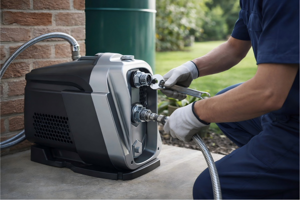
Struggling with low water pressure?
This common problem can disrupt daily tasks.
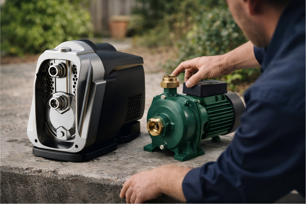
A pump is the solution, boosting pressure efficiently and providing a consistent flow for your needs.
A pump increases pressure by converting mechanical energy into fluid energy. It uses components like impellers or pistons to accelerate the fluid, increasing its kinetic energy, which is then converted into potential energy in the form of pressure as the fluid leaves the pump's discharge.
Understanding how a pump creates pressure is crucial for selecting the right equipment for your system.
It's not just about moving water; it's about adding energy to the system in a controlled way.
This process involves fundamental principles of physics and sophisticated engineering design, which differ significantly between pump types.
Let's explore the mechanics behind this essential function, breaking down the science into clear, understandable concepts.
By the end, you'll have a solid grasp of how these powerful devices work and how to choose the best one for your specific application, ensuring optimal performance and efficiency.
The Core Concept: Energy Conversion
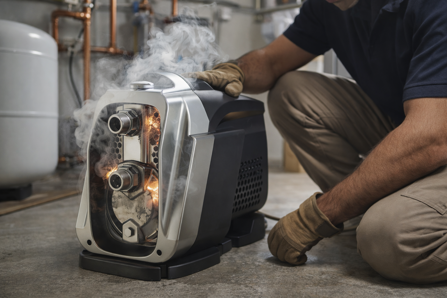
Experiencing inconsistent flow?
This can indicate an energy deficit in your water system.
A pump solves this by adding the necessary energy to create stable and reliable pressure.
At its core, a pump increases pressure by converting energy from one form to another. It takes mechanical energy from a motor and transfers it to the fluid, increasing the fluid's kinetic and potential energy, which we experience as higher pressure.
A pump does not create pressure out of thin air.
Instead, it acts as an energy converter.
The process begins with an external power source, typically an electric motor.
This motor provides rotational mechanical energy to the pump's shaft.
The pump's internal mechanism then uses this rotation to do work on the fluid passing through it.
This work results in a significant increase in the fluid's total energy.
Think of it like a baseball pitcher.
The pitcher's arm (the motor) provides mechanical energy to the ball (the fluid).
As the ball is thrown, its velocity (kinetic energy) increases dramatically.
A pump does something similar, but with a continuous flow of liquid.
The Physics Behind the Pressure Boost
The operation of a pump is governed by fundamental physics, primarily the principles of energy conservation.
The total energy of a fluid, as described by Bernoulli's principle, is a sum of its pressure energy, kinetic energy (from its velocity), and potential energy (from its height).
A pump adds energy to this equation, expressed as "pump head," which directly translates to a pressure increase.
| Energy Component | Description | Role in Pumping |
|---|---|---|
| Pressure Energy | The internal energy of the fluid due to the force it exerts. | This is the primary output we want to increase. |
| Kinetic Energy | The energy of the fluid due to its motion ( |
velocity). | Pumps often increase this first, then convert it to pressure. |
| Potential Energy | The energy of the fluid due to its elevation. | Pumping to a higher elevation directly increases potential energy. |
For instance, if a pump is drawing water from a ground-level tank and pushing it to a rooftop, it must overcome gravity (increasing potential energy) and friction losses while also delivering the desired pressure at the outlet.
A a pump with 75% efficiency means that 75% of the input mechanical energy is successfully transferred to the fluid as increased pressure and flow, with the remaining 25% lost to heat, friction, and noise.
Pump Head: The True Measure of Energy
In pump terminology, the energy added to the fluid is called "head."
Head is a more useful measure than pressure because it is independent of the fluid's specific gravity.
It is expressed in units of length (e.g., meters or feet).
Total Dynamic Head (TDH) is the total equivalent height that a fluid is to be pumped, taking into account friction losses in the pipe.
It's the sum of the static lift, static head, and friction loss.
A pump's performance is defined by its ability to generate a certain flow rate (Q) at a specific head (H).
This relationship is unique to each pump and is visualized on its performance curve.
Understanding this curve is essential for matching a pump to an application's specific requirements to ensure it operates at or near its Best Efficiency Point (BEP).
Centrifugal Pumps: The Velocity-to-Pressure Trade-off
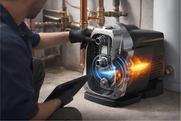
Need to move large volumes of water efficiently?
Standard pumps may struggle.
Centrifugal pumps are designed for high flow, using a smart process to convert velocity into reliable pressure.
A centrifugal pump uses a spinning impeller to throw fluid outwards at high velocity. The pump's casing, called a volute, then slows the fluid down, converting its high kinetic energy (velocity) into high potential energy (pressure) before it exits the discharge port.
The magic of a centrifugal pump lies in its elegant simplicity and efficiency.
The entire process is a masterful trade-off between velocity and pressure, governed by Bernoulli's principle.
It starts at the pump's inlet, or "eye" of the impeller.
As the motor spins the impeller, the curved vanes catch the fluid and accelerate it radially outwards.
This rapid acceleration imparts a large amount of kinetic energy to the fluid; its velocity increases dramatically.
Some testing shows that the fluid velocity can increase by over 200% within the impeller channels.
Once the high-velocity fluid leaves the tips of the impeller, its journey is only half complete.
It enters the volute, which is a snail-shaped, progressively widening chamber.
This increasing area forces the fluid to slow down.
According to the law of conservation of energy, the kinetic energy that is lost due to the decreasing velocity must be converted into another form.
In this case, it is converted into pressure energy, and the pressure of the fluid rises significantly.
This process allows centrifugal pumps to generate a smooth, non-pulsating flow, making them ideal for a wide range of applications, from residential water boosting to large-scale industrial processes.
Inside the Impeller: Where the Energy Transfer Begins
The impeller is the heart of any centrifugal pump.
Its design is critical to the pump's performance and efficiency.
There are three main types of impellers, each suited for different applications.
- Open Impeller: Has vanes attached to a central hub, but no sidewalls (shrouds).
They are structurally weaker but excel at handling fluids with suspended solids, as they are less likely to clog. - Semi-Open Impeller: Features a back wall (shroud) that adds mechanical strength, but the front side of the vanes remains open.
This offers a good compromise between solids-handling capability and efficiency. - Closed Impeller: Has shrouds on both sides of the vanes, creating a fully enclosed channel for the fluid.
This is the most efficient design, typically reaching efficiencies of 75-90%, as it minimizes recirculation and guides the fluid precisely.
However, it is best suited for clean liquids, as it can be easily clogged by solids.
The choice of impeller directly impacts the pump's ability to generate pressure and its suitability for the intended liquid.
The Volute's Role: The Art of Conversion
The volute is more than just a casing; it's a precisely engineered hydraulic component designed to manage the energy conversion process.
Its primary function is to collect the fluid from the impeller and guide it to the discharge nozzle while efficiently converting velocity head into pressure head.
The cross-sectional area of the volute increases gradually from a point called the "cutwater" around to the discharge port.
This design ensures a steady, gradual deceleration of the fluid.
A poorly designed volute can lead to significant energy losses, turbulence, and an unbalanced radial thrust on the impeller shaft, which can cause excessive vibration, bearing wear, and premature pump failure.
In multi-stage centrifugal pumps, diffusers are often used instead of or in addition to a volute.
Diffusers are stationary rings with multiple guide vanes that perform the same velocity-to-pressure conversion but can do so more efficiently in a more compact space, allowing for multiple stages to be stacked together to achieve extremely high pressures.
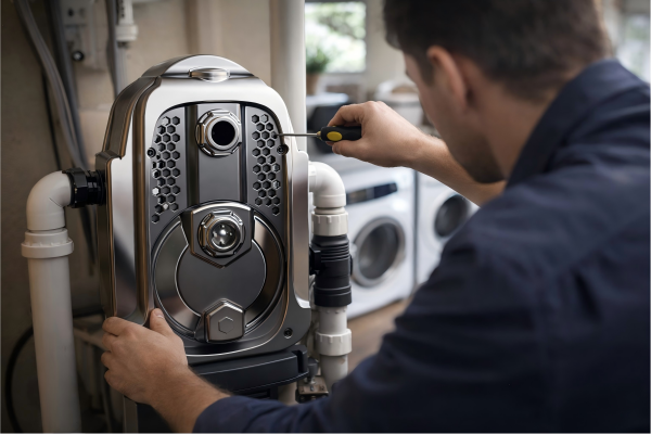
Positive Displacement Pumps: The Forceful Push
Need precise flow or very high pressure?
Centrifugal pumps might fall short.
Positive displacement pumps provide consistent flow regardless of pressure, trapping and forcing fluid through the system.
A positive displacement (PD) pump works by trapping a fixed volume of fluid in a chamber and then forcing it into the discharge pipe. The pressure increases because the fluid is incompressible and is being mechanically pushed against the system's resistance.
Unlike centrifugal pumps that convert velocity to pressure, positive displacement pumps operate on a more direct principle.
They physically displace, or push, the fluid.
Imagine using a syringe to inject liquid.
As you push the plunger, you trap a fixed volume of liquid and force it out.
The pressure of the liquid increases to whatever level is necessary to overcome the resistance at the needle's tip.
A PD pump works in the same way.
It doesn't create pressure; it simply provides a constant flow.
The system's resistance (from pipes, valves, nozzles, etc.) is what generates the back pressure.
Because PD pumps will continue to build pressure against a blockage, they are almost always installed with a pressure relief valve for safety.
This ability to deliver a constant flow rate, almost independent of the system pressure, makes them ideal for applications requiring precise dosing, metering, or handling high-viscosity fluids.
For example, gear pumps can handle liquids with viscosities up to 1 million centipoise, something a centrifugal pump could never do.
Reciprocating vs. Rotary: Two Approaches to Displacement
Positive displacement pumps are broadly categorized into two main families: reciprocating and rotary.
While both work by displacing fluid, their mechanisms are quite different.
-
Reciprocating Pumps: These pumps use a back-and-forth motion.
- Piston Pumps: A piston moves back and forth in a cylinder, drawing fluid in on the suction stroke and pushing it out on the discharge stroke.
- Diaphragm Pumps: A flexible diaphragm flexes back and forth, driven by a mechanical linkage or compressed air, to change the volume of the pumping chamber.
They are excellent for generating very high pressures, with some models exceeding 10,000 PSI (700 bar).
However, their flow is pulsating, which may be undesirable in some systems.
-
Rotary Pumps: These pumps use a rotating mechanism to move fluid.
- Gear Pumps: Meshing gears trap fluid between their teeth and the pump casing, carrying it from the inlet to the outlet.
- Lobe Pumps: Similar to gear pumps, but the lobes do not touch, making them suitable for shear-sensitive or solids-laden products.
- Screw Pumps: Two or more intermeshing screws rotate to move fluid axially along the pump.
Rotary pumps provide a smoother, more continuous flow than reciprocating pumps and are excellent at handling viscous liquids.
Pressure Generation and Safety
The pressure-generating characteristic of a PD pump is a defining feature.
Since the pump displaces a near-constant volume of fluid with each revolution or stroke, it will continue to do so against increasing back pressure.
If the discharge line were to be blocked, the pressure would rise until the motor stalled, a pipe burst, or the pump itself failed.
This is a critical safety consideration.
| Pump Type | Pressure Generation Method | Flow Characteristic | Safety Requirement |
|---|---|---|---|
| Centrifugal | Converts velocity to pressure. | Variable flow, dependent on pressure. | Generally safe on shut-off (for short periods). |
| Positive Displacement | Mechanically forces fluid. | Constant flow, independent of pressure. | Mandatory pressure relief valve. |
This is why a pressure relief valve is not an optional accessory but an essential safety component in virtually all PD pump systems.
This valve is set to a specific pressure limit.
If the system pressure exceeds this limit, the valve opens, diverting flow back to the suction side of the pump or to a tank.
This protects the pump, piping, and downstream equipment—as well as personnel—from dangerous over-pressurization events, which could occur in over 95% of blocked-outlet scenarios without such protection.
Factors Influencing Pressure Increase
Wondering why your pump isn't hitting the target pressure?
It's not just the pump's fault.
System design, fluid properties, and operational speed all play a crucial role in determining the final output.
The final pressure a pump achieves is influenced by the pump's speed (RPM), the impeller diameter (for centrifugal pumps), and the total system resistance, also known as the system head. Fluid properties like viscosity and density also have a significant impact.
A pump does not operate in a vacuum.
Its performance is a direct response to the system in which it is installed.
Understanding the factors that influence the final pressure is key to designing and troubleshooting any pumping system effectively.
For centrifugal pumps, the Affinity Laws provide a clear mathematical relationship between speed, flow, and pressure.
For example, doubling the pump's speed will not just double the pressure; it will quadruple it.
Similarly, increasing the impeller diameter has a squared effect on the pressure output.
This is why Variable Frequency Drives (VFDs) are so effective for controlling centrifugal pumps.
By precisely adjusting the motor's speed, a VFD can make the pump produce the exact pressure and flow required by the system, often saving 30-50% in energy consumption compared to a fixed-speed pump throttled with a valve.
System resistance, or the "system curve," is the other half of the equation.
It represents the pressure required to push fluid through the pipes, fittings, and valves at a given flow rate.
The pump's operating point is where its performance curve intersects with the system curve.
The Role of Fluid Properties
The type of fluid being pumped has a profound effect on pressure generation.
The pump's performance curve is typically based on testing with clean, cold water.
Any deviation from this baseline will alter the pump's output.
-
Density (Specific Gravity): The pressure a centrifugal pump can generate (in PSI or bar) is directly proportional to the fluid's density.
If a pump produces 50 PSI with water (SG = 1.0), it will only produce 45 PSI with a fluid that has a specific gravity of 0.9.
However, the head (in meters or feet) it produces will remain the same. The power required to drive the pump also increases directly with density. -
Viscosity: This is a measure of a fluid's resistance to flow.
High viscosity increases friction losses within the pump and the piping, reducing the effective flow and pressure.
Centrifugal pump performance degrades rapidly with even a moderate increase in viscosity.
For highly viscous fluids (e.g., honey, heavy oil), a positive displacement pump is almost always the correct choice, as its performance is much less affected.
System Design and Operational Parameters
How the system is built and operated is just as important as the pump itself.
Key System Considerations
- Pipe Diameter: Using undersized pipes is a common mistake.
It dramatically increases friction loss, forcing the pump to work harder to achieve the desired pressure at the end point.
Doubling the pipe diameter can reduce friction loss by a factor of 16. - Fittings and Valves: Every elbow, tee, and valve adds to the system's total resistance.
A streamlined pipe layout with minimal bends and appropriate valve selection is crucial for efficiency.
A single sharp 90-degree elbow can add as much friction as several feet of straight pipe. - Pump Speed (RPM): As mentioned with the Affinity Laws, speed is a powerful control parameter for centrifugal pumps.
Intelligent pumps use VFDs and pressure sensors to automatically adjust their speed to maintain a constant discharge pressure, regardless of changes in demand.
This provides both stable operation and maximum energy efficiency, which can lead to a return on investment in under two years for many applications.
| Factor | Effect on Pressure | Typical Impact |
|---|---|---|
| Increase Pump Speed | Increases Pressure (Squared) | A 10% speed increase yields a ~21% pressure increase. |
| Increase Fluid Viscosity | Decreases Effective Pressure | Reduces flow and head, increases power draw. |
| Decrease Pipe Diameter | Increases Friction Loss (Reduces end pressure) | Halving pipe diameter can increase friction ~16x. |
| Static Head | Adds a constant pressure requirement | The pump must overcome this elevation difference first. |
Ultimately, achieving the desired pressure is a balancing act between selecting the right pump and designing an efficient system for it to work in.
Pump Performance Curves: The Visual Guide
How do you know if a pump is right for your job?
Guesswork leads to costly errors.
Pump performance curves provide a detailed map of a pump's capabilities, ensuring a perfect match for your needs.
A pump performance curve is a graph that shows the relationship between the pump's flow rate (Q) and the head (H) it produces. It also typically includes curves for efficiency, power consumption (BHP), and Net Positive Suction Head required (NPSHr).
The performance curve is the single most important piece of data for a pump.
It is generated by the manufacturer through rigorous testing and represents the pump's hydraulic "fingerprint."
By learning to read this graph, you can accurately predict how a pump will behave in your specific system.
The main curve, Head vs.
Flow, is the most prominent.
It shows that as the flow rate increases, the head (pressure) the pump can generate decreases.
At zero flow (shut-off head), the pressure is at its maximum.
As flow increases, the pressure drops along a predictable curve.
The system curve, which represents your piping system's resistance, is overlaid on this graph.
The point where the two curves intersect is the pump's operating point—the actual flow and pressure you will get.
The goal is to select a pump where this operating point falls on or near its Best Efficiency Point (BEP).
The BEP is the point on the curve where the pump is using the least amount of energy to move the most amount of water, often indicated by the peak of the efficiency curve.
Operating a pump far from its BEP (more than 10-15% away) can lead to high energy costs, increased vibration, and a significantly reduced operational life.
Deconstructing the Curve: Key Elements
A complete pump curve provides a wealth of information beyond just head and flow.
Understanding each element is vital for proper pump selection and system analysis.
Primary Curves Explained
- Head-Flow (H-Q) Curve: The primary curve showing the inverse relationship between head and flow rate.
The shape of this curve (e.g., steep, flat) tells you how the pump's pressure will respond to changes in flow demand. - Efficiency Curve: This inverted "U" shaped curve shows the pump's mechanical efficiency at each point along the H-Q curve.
The highest point of this curve is the Best Efficiency Point (BEP).
High-efficiency pumps can have BEPs exceeding 85%. - Power (BHP) Curve: This shows the Brake Horsepower (BHP), which is the actual power required from the motor at a given flow rate.
This is crucial for selecting a motor that is powerful enough but not oversized, which would be inefficient.
For centrifugal pumps, power generally increases with flow. - NPSHr Curve: The Net Positive Suction Head required (NPSHr) is the minimum pressure needed at the pump's suction port to prevent cavitation.
Cavitation is a destructive phenomenon where vapor bubbles form and then implode, causing noise, vibration, and damage to the impeller.
The Net Positive Suction Head available (NPSHa) from your system must always be greater than the pump's NPSHr.
Using the Curve for Selection
To select a pump, you first need to determine your system's requirements: the desired flow rate and the total head the pump must overcome.
- Calculate System Head: This includes static head (elevation changes) and friction head (losses in pipes and fittings).
- Determine Flow Rate: This is the volume of fluid you need to move per unit of time (e.g., gallons per minute or cubic meters per hour).
- Plot the Operating Point: Find the point on a graph that corresponds to your required head and flow.
- Select a Pump: Choose a pump whose performance curve passes through or very close to your desired operating point.
Critically, this operating point should also be near the pump's BEP (typically within 80-110% of the BEP flow rate) to ensure efficient and reliable operation.
Investing time in a proper analysis using pump curves can prevent costly issues like undersized pumps, oversized motors, high energy bills, and frequent maintenance.
It is the cornerstone of professional and efficient fluid system design.
Conclusion
A pump increases pressure by converting mechanical energy into fluid energy.
This is achieved either by converting velocity to pressure in centrifugal pumps or by direct mechanical force in positive displacement pumps.
FAQs
What is the basic principle of a pump?
A pump's basic principle is to add energy to a fluid.
It converts mechanical energy from a motor into hydraulic energy, increasing the fluid's pressure and causing it to flow.
What is the difference between pressure and head in a pump?
Pressure is force per unit area, dependent on the fluid's density.
Head is the height of a liquid column the pump can support, independent of density, making it a universal performance measure.
Why do pumps have a BEP?
The Best Efficiency Point (BEP) is the flow rate where the pump's internal hydraulic design is most effective.
At this point, energy losses are minimized, and efficiency is maximized.
What happens if you run a centrifugal pump with the discharge valve closed?
Running it closed (dead-heading) causes maximum pressure but zero flow.
The energy converts to heat, which can quickly damage the pump's internal components if done for too long.
How does a variable frequency drive (VFD) save energy?
A VFD saves energy by adjusting the pump's motor speed to match the exact flow and pressure demand.
This avoids wasting energy by throttling a fixed-speed pump with a valve.
What is pump cavitation and why is it bad?
Cavitation is the formation and collapse of vapor bubbles inside a pump.
This is highly destructive, causing noise, vibration, and severe erosion of the impeller and casing materials.
Can I pump hot water with a standard pump?
Pumping hot water requires careful consideration.
The water's higher vapor pressure increases the risk of cavitation, so you need to ensure the available suction head (NPSHa) is sufficient.
How do I choose between a centrifugal and a positive displacement pump?
Choose a centrifugal pump for high-flow, low-viscosity applications.
Use a positive displacement pump for low-flow, high-pressure, or high-viscosity applications, or when precise dosing is needed.