Your business depends on reliable products.
Finding a pump supplier you can trust is a constant challenge.
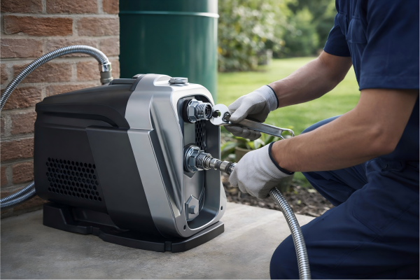
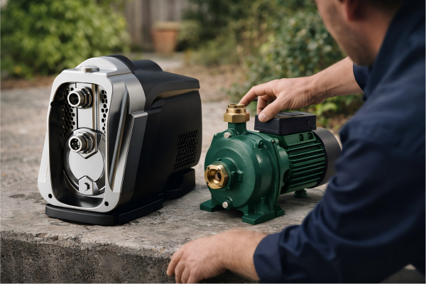
You need a partner who understands every step of the manufacturing process, ensuring quality from raw material to final product.
A pump is manufactured through a multi-stage process. This begins with material sourcing and casting of components like the housing and impeller. It then proceeds a to a machining, motor assembly, final assembly, and a rigorous series of up to 100% performance and safety tests before packaging.
Understanding the intricate process of pump manufacturing is vital for any importer or distributor.
It provides insight into the quality, durability, and performance of the products you source.
A transparent manufacturing process, from initial design to the final quality check, is the bedrock of a successful and reliable supply chain.
This knowledge empowers you to make better purchasing decisions.
It helps you partner with manufacturers who meet the highest standards of excellence.
Let's explore the key stages that transform raw materials into high-performance water pumps.
What Are the Core Components of a Water Pump?
Sourcing pumps can feel like a black box.
You see the finished product but not the critical parts inside.
Understanding these components is key to judging quality and ensuring you're not buying products prone to failure.
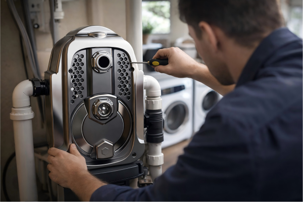
Every water pump consists of essential components working together. Key parts include the casing (volute), which contains everything; the impeller, which moves the water; a motor to power the impeller; and seals to prevent leaks. The quality of each part determines overall pump performance and longevity.
A deeper look at these components reveals how they contribute to the pump's overall function and quality.
The specifics of each part can vary significantly between manufacturers, directly impacting efficiency and reliability.
For business owners like you, knowing these details is not just technical trivia; it's a crucial part of supplier validation.
It allows you to ask the right questions and identify a manufacturer committed to quality engineering.
The Heart of the Pump: Impeller and Motor
The impeller is arguably the most critical component for a pump's performance.
Its design, material, and balance directly affect the flow rate, pressure, and efficiency.
There are several types of impellers:
- Open Impellers: These are structurally weaker but are best for handling solids. They are easier to clean and maintain.
- Semi-Open Impellers: This type offers a balance of strength and solids-handling capability.
- Closed Impellers: These are the most common in clean water applications. They offer the highest efficiency but can clog with solids.
The motor is the powerhouse.
Its quality determines the pump's energy consumption, operational lifespan, and reliability.
Key motor considerations include winding material (copper is superior to aluminum), insulation class, and the Ingress Protection (IP) rating, which indicates its resistance to dust and water.
A motor with a higher efficiency rating can reduce operational costs by over 15% annually.
The Protective Shell: Casing and Seals
The casing, or volute, does more than just hold the parts together.
It is designed to channel the water from the impeller, converting velocity into pressure.
The material of the casing is vital for durability.
| Casing Material | Primary Advantage | Common Application |
|---|---|---|
| Cast Iron | Cost-effective and strong | General-purpose, clean water |
| Stainless Steel | Corrosion-resistant | Food-grade, chemical, marine |
| Bronze | Saltwater corrosion-resistant | Marine applications |
| Thermoplastics | Lightweight, chemical-resistant | Small domestic, pool pumps |
Mechanical seals are unsung heroes.
They prevent leaks between the rotating shaft and the stationary pump casing.
A seal failure can lead to motor damage and complete pump failure.
High-quality seals are made from materials like ceramic, carbon, or silicon carbide, chosen based on the fluid being pumped and the operating temperature.
Investing in superior seals can increase a pump's mean time between failures (MTBF) by as much as 50%.
How Does the Design and Prototyping Phase Work?
Your market demands innovative and reliable products.
A pump that looks good on a spec sheet might fail in the real world.
You need to know if your supplier's design process is rigorous enough to catch flaws before they reach your customers.
The design and prototyping phase uses Computer-Aided Design (CAD) and simulation software to create a digital model of the pump. This model is analyzed for hydraulic efficiency and structural integrity. A physical prototype is then built and tested to validate the digital simulations and refine the design.
This initial phase is where a pump's success or failure is often decided.
It's a meticulous process that combines advanced software with hands-on engineering to create a product that is not only functional but also efficient, durable, and cost-effective to manufacture.
A manufacturer with a strong R&D department, holding dozens of technical patents, demonstrates a commitment to innovation and quality that goes beyond simple assembly.
This is the foundation upon which a reliable product is built.
From Concept to Digital Model
The process begins with defining the pump's objectives.
What is its target application?
What flow rate and pressure are required?
What are the constraints on size, power consumption, and cost?
Engineers use this data to create initial concepts.
These concepts are brought to life using 3D CAD software.
Every component is modeled with precise dimensions and material properties.
This digital blueprint is far more than just a picture.
It is a comprehensive data set that allows for advanced analysis.
Simulation and Analysis
Before any metal is cut, the digital prototype undergoes extensive testing in a virtual environment.
Computational Fluid Dynamics (CFD) is a critical tool used in this stage.
- CFD analysis simulates the flow of water through the pump. It helps engineers optimize the shape of the impeller and volute to maximize efficiency and minimize issues like cavitation, which can destroy a pump.
- Finite Element Analysis (FEA) tests the structural integrity of the components. It applies virtual pressures and stresses to identify potential weak points in the casing, shaft, or impeller, preventing physical failures down the line.
This simulation-driven approach can improve hydraulic efficiency by 5-10% and reduce material usage without compromising strength.
It dramatically shortens the development cycle and lowers prototyping costs.
Physical Prototyping and Validation
Once the digital design is optimized, a physical prototype is created.
This is often done using rapid prototyping techniques like 3D printing or CNC machining.
The prototype is then subjected to a battery of real-world tests on a dedicated test bench.
| Test Parameter | Purpose | Success Metric |
|---|---|---|
| Performance Curve | Verify flow, head, and efficiency vs. digital model | Within 3-5% of CFD simulation predictions |
| NPSHr Test | Determine susceptibility to cavitation | Meets or exceeds design specifications |
| Endurance Test | Assess long-term reliability under load | 1000+ hours of continuous operation |
| Noise & Vibration | Check for smooth operation and balance | Within acceptable ISO standard limits |
Data from these physical tests provides a feedback loop.
The results are used to make final adjustments to the CAD model before the design is approved for mass production.
This iterative process ensures the final product is thoroughly vetted and meets all performance claims.
What Materials Are Used in Pump Manufacturing?
Product longevity directly impacts your reputation.
Choosing a pump made from substandard materials leads to premature failures.
This results in warranty claims and dissatisfied customers, harming your brand.
Pump manufacturing uses a range of materials selected for strength, corrosion resistance, and cost-effectiveness. The pump body is often cast iron or stainless steel. The impeller can be stainless steel, bronze, or engineered plastics. The motor shaft is typically high-grade stainless steel for strength and rust prevention.
The choice of materials is one of the most critical decisions in the manufacturing process.
It dictates the pump's suitability for different applications, from clean household water to corrosive industrial fluids.
A manufacturer's material sourcing and quality control protocols, like a structured IQC (Incoming Quality Control) system, are essential.
They ensure that only certified, high-quality raw materials enter the production line, forming the basis of a durable and reliable end product.
The Foundation: Casting and Forging
The main structural components of a pump, like the casing and motor housing, are typically made from cast iron or stainless steel.
Casting is the process of pouring molten metal into a mold to form the desired shape.
- Sand Casting: Cost-effective for complex shapes and large parts. The surface finish is rougher.
- Investment Casting (Lost-Wax): Provides a much smoother surface finish and tighter dimensional tolerances. It is more expensive but often reduces the need for subsequent machining. Used for high-performance components like stainless steel impellers.
For critical high-stress parts like shafts, forging is sometimes used.
Forging involves shaping metal using localized compressive forces, which aligns the grain structure of the metal and results in superior strength and fatigue resistance compared to casting.
The Dynamic Duo: Impeller and Shaft Materials
The impeller and shaft are subjected to constant stress and motion.
Their material composition is crucial for long-term reliability.
Impeller Materials:
- Noryl/PPO (Engineered Plastic): Lightweight, corrosion-proof, and good for clean water. Lower cost.
- Brass/Bronze: Excellent resistance to corrosion, especially in saltwater. Softer than steel.
- Cast Iron: Durable and low-cost, but susceptible to rust if not coated.
- Stainless Steel (AISI 304/316): Offers the best combination of strength, corrosion resistance, and efficiency. AISI 316 is preferred for more corrosive environments. A stainless steel impeller can last over three times longer than a plastic one in abrasive conditions.
Shaft Materials:
The shaft must be strong to transmit torque from the motor to the impeller and highly resistant to corrosion.
- Carbon Steel: Strong and inexpensive but requires protective coatings or sleeves to prevent rust.
- Stainless Steel (AISI 304): A common choice offering a great balance of strength, corrosion resistance, and cost.
- Stainless Steel (AISI 316): Used in more demanding applications where higher corrosion resistance is needed.
Beyond Metal: Seals, Gaskets, and Coatings
A pump's reliability depends on more than just its major metal parts.
Mechanical Seals: As discussed, these are critical. Common face materials include Carbon, Ceramic, and Silicon Carbide (SiC). SiC is extremely hard and wear-resistant, ideal for applications with abrasive particles.
Gaskets and O-Rings: These are typically made from elastomers like NBR, EPDM, or Viton. The choice depends on the fluid compatibility and temperature range. EPDM is excellent for water, while Viton is used for more aggressive chemicals and higher temperatures.
Coatings:
High-quality coatings provide an essential layer of protection.
- Electrophoretic Coating (E-coating): Provides a uniform, durable, and corrosion-resistant finish on cast iron parts, extending their life in damp environments by over 200%.
- Powder Coating: Offers a thick, durable finish that is resistant to chipping and scratching.
A manufacturer's commitment to using high-grade, certified materials for every single component is a clear indicator of their overall quality standards.
How Is Quality Controlled Throughout Production?
Inconsistent product quality erodes trust and profits.
Receiving a shipment with a high defect rate is a nightmare.
You need a manufacturing partner with a robust, multi-stage quality control system that prevents defects, rather than just catching them at the end.
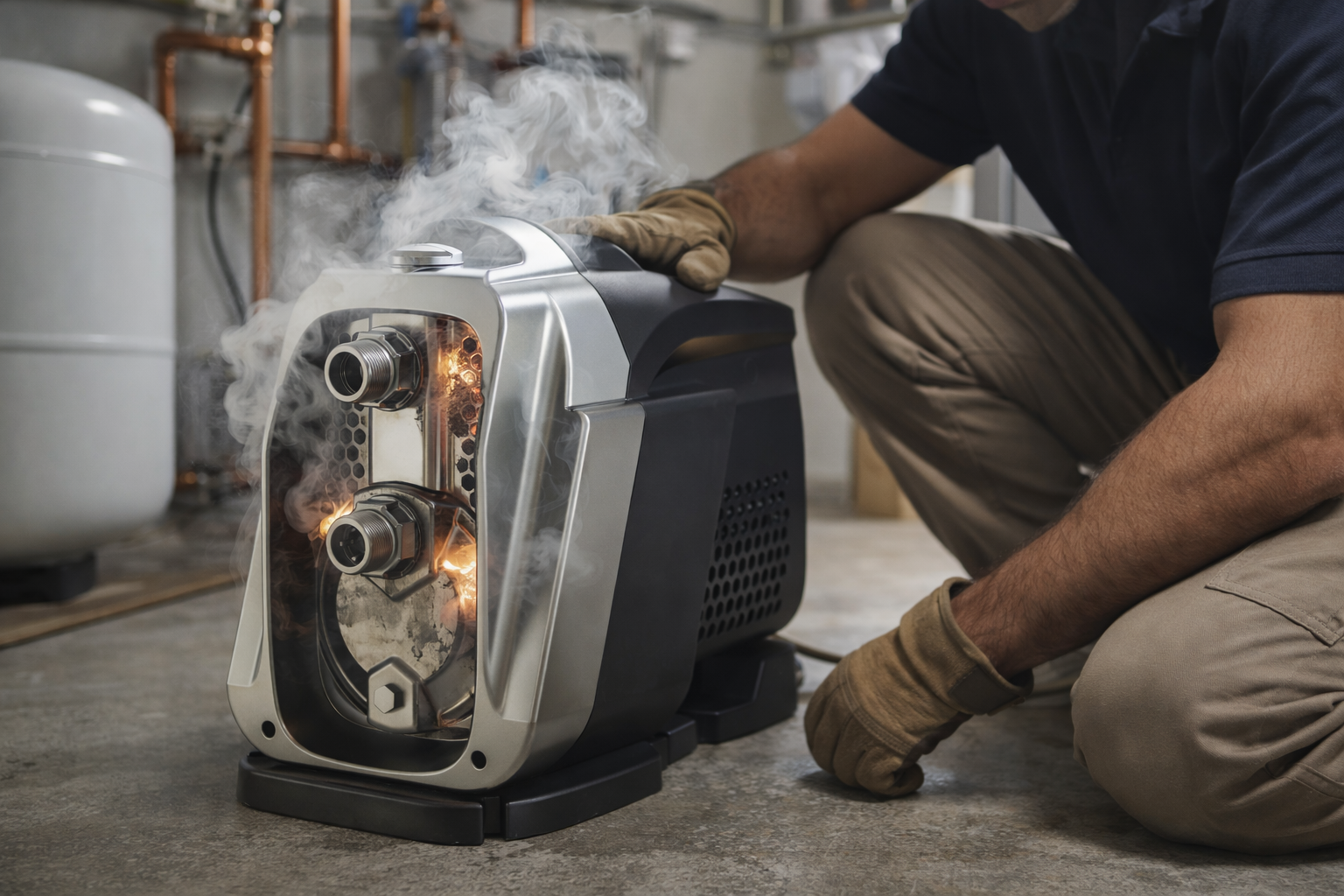
Quality is controlled through a structured system with checks at every stage. This includes Incoming Quality Control (IQC) for raw materials, In-Process Quality Control (IPQC) during machining and assembly, and Final Quality Control (FQC) where every finished pump is tested before shipment.
A truly quality-focused manufacturer doesn't treat quality control as a final step.
Instead, they embed it into every phase of the production process.
This systematic approach, sometimes called Total Quality Management (TQM), is designed to ensure that standards are met consistently.
For an importer, understanding a supplier's QC methodology is just as important as understanding their products.
It is the best predictor of long-term product reliability and a smooth business partnership.
The Four Pillars of Production QC
A comprehensive quality system can be broken down into key stages, each with a specific purpose.
| QC Stage | Acronym | Responsibility | Key Metrics Tracked |
|---|---|---|---|
| Incoming Quality Control | IQC | Inspecting and verifying all raw materials and components from sub-suppliers. | Material composition, dimensional accuracy, hardness. |
| In-Process Quality Control | IPQC | Monitoring and controlling quality during the manufacturing processes. | Machining tolerances, assembly torque, motor winding resistance. |
| Final Quality Control | FQC | 100% testing of every finished product before it is packaged. | Hydraulic performance, electrical safety, leak tests. |
| Outgoing Quality Assurance | OQA | Randomly sampling packaged products to ensure they meet all final specifications. | Packaging integrity, correct labeling, included accessories. |
This multi-layered approach ensures that potential issues are identified and corrected early, which is far more efficient and effective than finding problems at the final inspection.
Precision in Practice: Machining and Winding
After casting, components like the pump casing and impeller must be machined to precise tolerances.
Computer Numerical Control (CNC) machines are essential here.
They can achieve tolerances as tight as 0.01mm, ensuring a perfect fit between parts.
This precision is critical for pump efficiency and minimizing vibration.
IPQC inspectors use tools like Coordinate Measuring Machines (CMM) and digital calipers to verify these dimensions at regular intervals.
Motor winding is another critical process.
Automated winding machines ensure consistency, but quality control is still paramount.
Tests performed during this stage include:
- Winding Resistance Test: Ensures the correct length and gauge of copper wire were used.
- Hipot Test (High Potential): Checks the integrity of the insulation by applying a high voltage, preventing electrical shorts.
- Surge Test: Detects weak points in the winding insulation that could lead to premature motor failure.
A manufacturer that can demonstrate these rigorous IPQC checks is one that is serious about building a reliable motor.
The Final Gauntlet: 100% Product Testing
The most critical phase is the Final Quality Control, where every single pump is tested.
This is a non-negotiable step for any reputable manufacturer.
A dedicated test bench is used to run each pump through a series of performance and safety checks.
- Hydraulic Performance Test: The pump is connected to a system that measures its flow rate, pressure (head), and power consumption to ensure it meets its advertised performance curve.
- Leak Test: The pump is pressurized to check for any leaks from seals or gaskets.
- Electrical Safety Test: This includes tests for grounding continuity and insulation resistance to ensure the product is safe for the end-user.
Only pumps that pass 100% of these tests are sent to packaging.
This commitment to individual testing can reduce field failure rates to less than 0.1%.
What Happens During Final Assembly and Testing?
The final steps of production can make or break product quality.
Even with perfect components, improper assembly or rushed testing can lead to failures.
You need assurance that the end of the line is just as rigorous as the beginning.
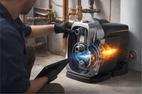
During final assembly, skilled technicians build the pump on a dedicated production line, fitting the motor, seals, impeller, and casing together. The fully assembled pump then undergoes 100% functional testing for hydraulic performance, electrical safety, and leak integrity before being painted, labeled, and packaged.
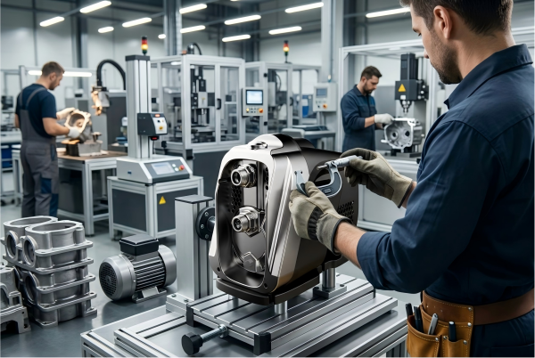
The final assembly line is where all the carefully crafted and controlled components come together.
An organized, well-lit, and efficient assembly line operated by trained technicians is a hallmark of a professional manufacturing operation.
Following assembly, the final testing stage acts as the ultimate gatekeeper of quality.
This is not a spot-check.
It is a comprehensive evaluation of every single unit that will be shipped, ensuring it performs exactly as designed and is completely safe for the end user.
The Assembly Line: A Symphony of Precision
Modern pump manufacturing facilities often utilize a multi-station assembly line.
Each station is responsible for a specific set of tasks, allowing workers to become specialists in their area.
This improves both speed and accuracy.
- Motor Sub-Assembly: The stator, rotor, bearings, and shaft are assembled into the motor housing. Clearances and fits are checked with precision gauges.
- Seal Installation: The mechanical seal is carefully pressed into the pump backplate. This is a delicate operation, as even a minor misalignment can cause a leak.
- Impeller Mounting: The impeller is mounted on the shaft. The clearance between the impeller and the volute (casing) is a critical dimension that is carefully set to maximize efficiency.
- Final Casing Assembly: The motor and backplate assembly are bolted to the main pump casing. Torque wrenches are used to ensure every bolt is tightened to the precise specification, creating a perfect seal.
Throughout this process, line quality control (LQC) personnel monitor each station to ensure procedures are being followed correctly.
Rigorous Final Testing Protocols
As mentioned, 100% testing is a mark of quality.
Here's a more detailed look at the final test sequence for a variable speed drive (VSD) pump:
| Test Name | Description | Why It's Critical |
|---|---|---|
| Dry Run & Noise Test | The pump is run briefly without water to check for abnormal noises or vibrations caused by imbalance. | Catches misaligned parts or defective bearings before the full performance test. |
| Hydrostatic Leak Test | The pump is filled with water and pressurized to 1.5 times its maximum operating pressure. | Guarantees the integrity of all seals, gaskets, and casing joints under stress. |
| Performance Curve Plot | The pump is run at various flow rates, and its head (pressure) and power draw are recorded. | Confirms the pump meets its advertised H-Q (Head-Flow) performance specifications. |
| VSD Function Test | The constant pressure function is tested by varying the system's demand to see if the pump adjusts speed. | Verifies the intelligent control unit and pressure sensor are working correctly. |
| Electrical Safety | Includes ground continuity, insulation resistance, and hipot tests on the fully assembled product. | Ensures the product is 100% safe and complies with international standards like CE and IEC. |
Only after passing every single one of these tests is a pump given a unique serial number and a passing quality certificate.
Finishing Touches: Painting and Packaging
The final step is preparing the pump for its long journey.
The pump is cleaned and then painted.
A multi-layer painting process, often starting with a corrosion-resistant primer, ensures a durable finish that can withstand harsh environments.
Testing might include 144+ hours of salt spray testing to validate the coating's effectiveness.
Finally, the pump is packaged with its instruction manual and any accessories.
The packaging itself is designed to protect the product from shock and vibration during shipping, ensuring it arrives at your warehouse in perfect condition.
Conclusion
A pump's journey from raw material to a finished product is complex.
It involves precise design, quality materials, and rigorous, multi-stage testing to ensure reliability, efficiency, and safety for the end-user.
FAQs
What determines the quality of a water pump?
The quality is determined by the grade of materials used, the precision of the manufacturing process, and the rigor of the 100% final testing protocols for performance and safety.
How do you manufacture a pump?
A pump is made by designing components, casting or forging parts from raw materials like iron, machining them to precise tolerances, assembling the motor and hydraulics, and then testing each unit completely.
What is the manufacturing process of a centrifugal pump?
The process involves casting a volute (casing) and an impeller, precisely machining both, assembling them with a motor and seals, and then performance testing to verify the specific head and flow characteristics.
What is the life of a water pump?
The lifespan of a quality water pump can be 15 to 20 years or more. This depends on the quality of its components, proper installation, and regular maintenance.
Why do water pumps fail?
Common causes of failure include seal leaks leading to motor damage, bearing failure from vibration or contamination, and motor burnout from overheating or electrical issues. Many are preventable with quality manufacturing.
Can a water pump be repaired?
Yes, many water pumps can be repaired. Common repairs include replacing mechanical seals, bearings, or capacitors. However, for smaller pumps, replacement is often more cost-effective.
How often should a water pump be serviced?
A well pump should be professionally inspected every one to two years. This helps catch minor issues with the pressure tank, switch, and motor before they cause a major failure.
What maintenance does a water pump require?
Maintenance includes regularly checking for leaks, listening for unusual noises, ensuring ventilation for the motor is clear, and testing the pressure switch and tank to ensure they are functioning correctly.