Choosing the wrong irrigation pump wastes energy and money.
An undersized pump fails to deliver water, while an oversized one skyrockets your power bills by over 20%.
Follow this guide to size it perfectly.
To size an irrigation pump, you must calculate two core metrics: the required flow rate (in GPM or m³/h) and the Total Dynamic Head (TDH) of your system.
These values are essential for matching a pump to its Best Efficiency Point (BEP), ensuring optimal performance and energy savings.
Getting these numbers right is the foundation of an efficient irrigation system.
But what do these terms mean, and how do you calculate them for your specific project?
Let's break down the entire process step-by-step.
This guide will walk you through everything from basic principles to advanced considerations, ensuring you can confidently select the right pump for any application.
Understanding Key Metrics: Flow Rate (GPM) and Total Dynamic Head (TDH)
Confused by pump terminology?
Terms like "flow rate" and "TDH" can seem complex, often leading to incorrect pump selection and system failures.
Let's simplify these foundational concepts.
Flow rate, measured in Gallons Per Minute (GPM) or cubic meters per hour (m³/h), is the volume of water the pump moves over time.
Total Dynamic Head (TDH), in feet or meters, is the total pressure the pump must overcome to move that water effectively.
These two metrics are the language of pump performance.
They are not just technical terms; they are the critical data points that dictate whether your irrigation system will succeed or fail.
A pump is designed to operate within a specific range of flow and pressure.
If your system's requirements fall outside this range, you will face problems.
These issues can include low pressure at the sprinklers, pump damage from cavitation, or energy consumption that is 30-50% higher than necessary.
Mastering these two concepts is the first and most important step in the pump selection process.
What is Flow Rate (Q)?
Flow rate is the volume of water your pump can move in a set amount of time.
It is often abbreviated as 'Q'.
You can think of it as the speed at which you are filling a bucket.
A higher flow rate means you fill the bucket faster.
In irrigation, flow rate determines how much land you can water simultaneously.
This metric is commonly measured in:
- Gallons Per Minute (GPM) in the United States.
- Cubic meters per hour (m³/h) in countries using the metric system.
- Liters per minute (L/min) or liters per second (L/s) are also used.
Understanding your required flow rate is essential.
It directly influences the number of sprinklers, drippers, or emitters you can run at once without losing performance.
Without an accurate flow rate calculation, you risk creating dry spots in your field or overloading your water source.
What is Total Dynamic Head (TDH)?
Total Dynamic Head (TDH) represents the total work your pump needs to do.
It is the total equivalent height that water must be lifted, considering all sources of pressure loss.
TDH is the sum of three main components.
| Component | Description |
|---|---|
| Static Head | The vertical distance (elevation change) in feet or meters from the water source to the highest outlet. |
| Pressure Head | The pressure required at the end of the line for sprinklers or emitters to operate correctly. |
| Friction Head | The pressure lost due to friction as water moves through pipes, valves, and fittings. |
Calculating TDH is more complex than measuring flow rate.
It requires you to account for the physical layout of your entire irrigation system.
Ignoring any of these components will result in an undersized pump that cannot deliver water with enough pressure, rendering the system ineffective.
A pump must generate enough force to overcome the TDH to deliver the desired flow rate.
Calculating Your System's Flow Rate Requirement
Your irrigation system has a specific water demand.
Failing to meet this demand results in under-watered crops and reduced yields.
Guessing the flow rate leads to costly mistakes.
To calculate your system's required flow rate, sum the individual flow rates of all sprinklers or emitters that will operate at the same time.
This total represents the demand your pump must meet.
For example, 10 sprinkler heads needing 5 GPM each require a 50 GPM pump.
This calculation seems simple, but its accuracy is paramount.
It forms the first half of the equation for proper pump sizing.
An inaccurate flow rate calculation is a common source of error.
Many people only consider the size of the area they need to irrigate.
However, the specific type and number of water delivery devices are what truly determine the required flow.
You must gather data directly from the manufacturer specifications for your chosen sprinklers, drip lines, or other emitters.
This ensures your calculations are based on real-world requirements, not assumptions.
We will now explore how to determine this value for different types of irrigation systems and how to plan for future expansion.
Step 1: Determine the Total Area and Irrigation Zones
First, measure the total area you need to irrigate.
This is usually measured in square feet, square meters, or acres.
Large areas are almost always divided into smaller, manageable sections called zones.
Zones are groups of sprinklers or drip lines that run at the same time.
You rarely water the entire property at once.
This is because most water sources and pumps cannot handle the massive flow rate required.
Dividing the system into zones allows you to use a smaller, more energy-efficient pump.
Your goal is to calculate the flow rate for the single largest zone.
The pump only needs to be large enough to supply the zone with the highest water demand, as zones will be operated one at a time.
Step 2: Find the Flow Rate of Individual Emitters
Every sprinkler, rotor, and drip emitter has a specific flow rate.
This information is provided by the manufacturer.
It is usually expressed in GPM or L/min.
Look for a specification sheet or product manual for your chosen equipment.
The flow rate often varies with the operating pressure.
For example, a spray head might deliver 1.5 GPM at 30 PSI but 1.8 GPM at 40 PSI.
It is critical to use the flow rate that corresponds to the recommended operating pressure for that emitter.
| Emitter Type | Typical Operating Pressure (PSI) | Typical Flow Rate (GPM) |
|---|---|---|
| Pop-Up Spray Head | 20 - 30 PSI | 0.5 - 4.0 GPM |
| Rotor Sprinkler | 30 - 60 PSI | 2.0 - 15.0 GPM |
| Drip Emitter | 10 - 25 PSI | 0.016 - 0.033 GPM |
| Micro-Sprayer | 15 - 30 PSI | 0.2 - 1.0 GPM |
Step 3: Calculate the Total Flow Rate for the Largest Zone
Once you have the flow rate for each emitter, you can calculate the total flow for each zone.
Simply add up the flow rates of all emitters within a single zone.
Zone Flow Rate = (Number of Emitters in Zone) x (Flow Rate per Emitter)
Do this calculation for every zone in your system.
The highest value among all your zones is your system's required flow rate.
This is the number you will use to size your pump.
For instance, if Zone 1 requires 45 GPM and Zone 2 requires 50 GPM, your pump must be able to deliver at least 50 GPM.
It is also wise to add a small buffer of 10-15% to account for future system wear and potential minor expansions.
Determining the Total Dynamic Head (TDH) of Your System
You've calculated your flow rate, but that's only half the battle.
Without enough pressure, that water is useless.
A pump that ignores TDH will fail to push water where it needs to go.
To determine TDH, you must add three values: the static head (vertical lift), the required pressure head at the outlets, and the total friction head loss from your piping system.
This sum represents the total resistance your pump must overcome.
Calculating Total Dynamic Head is the most technical part of sizing a pump, but it is not impossible.
It requires careful measurement and consulting some charts.
Breaking it down into its three core components makes the process manageable.
Getting this wrong is why many irrigation systems suffer from low pressure and poor performance, with sprinklers failing to create their full spray pattern.
A precise TDH calculation ensures your chosen pump delivers water at the right pressure everywhere in the system.
Let's dissect each component of the TDH equation.
Component 1: Calculating Static Head
Static head is the easiest part of TDH to calculate.
It is simply the vertical distance from the surface of your water source to the highest point in your irrigation system.
Measure this elevation change in feet or meters.
If you are pumping from a well, start your measurement from the pumping water level (the level the water drops to when the pump is running), not the static water level.
If you are pumping uphill to a field, the highest sprinkler head is your endpoint.
Static Head = (Elevation of Highest Outlet) - (Elevation of Water Source Surface)
For example, if your pump is pulling water from a lake and the highest sprinkler head is 25 feet above the lake's surface, your static head is 25 feet.
This value represents the raw lifting work the pump must do before accounting for any other factors.
Component 2: Determining Pressure Head
Your sprinklers or emitters need a certain amount of pressure to function correctly.
This is known as the operating pressure.
The pump must supply this pressure at the end of the line.
This requirement must be converted into "head."
The conversion is straightforward.
Pressure Head (in feet) = Operating Pressure (in PSI) x 2.31
Pressure Head (in meters) = Operating Pressure (in Bar) x 10.2
For example, if your rotor sprinklers require 40 PSI to operate, the pressure head is 40 x 2.31 = 92.4 feet.
Your pump must be powerful enough to provide this pressure after overcoming the static lift and all friction losses.
Always use the manufacturer's recommended operating pressure for this calculation to ensure optimal coverage and water distribution.
Component 3: Estimating Friction Head Loss
Friction head is the most complex component to calculate.
It represents the energy lost as water rubs against the inside of pipes, valves, and fittings.
Several factors influence friction loss:
- Pipe Diameter: Smaller pipes cause significantly more friction.
- Pipe Length: Longer pipes result in more total friction.
- Flow Rate: Higher flow rates dramatically increase friction.
- Pipe Material: Rougher materials (like old iron pipe) have more friction than smooth ones (like PVC).
- Fittings: Every elbow, tee, and valve adds to the friction.
To calculate this, you will need a friction loss chart for your specific pipe type (e.g., Schedule 40 PVC).
These charts show the friction loss in feet of head per 100 feet of pipe for various flow rates and pipe diameters.
Find your flow rate (e.g., 50 GPM) and pipe size (e.g., 2-inch) on the chart.
The chart might tell you the loss is 2.1 feet per 100 feet of pipe.
If your total pipe run is 500 feet, the friction loss for the pipe is (500 / 100) * 2.1 = 10.5 feet.
You must also add losses from fittings, which are often estimated as a percentage (e.g., 10%) of the pipe friction loss.
Total TDH = Static Head + Pressure Head + Friction Head
Reading and Interpreting a Pump Performance Curve
You have your target flow rate and TDH.
Now you must find a pump that meets these needs.
Choosing a pump based only on its maximum ratings is a recipe for inefficiency and premature failure.
You'll get a pump that's all wrong for your system.
A pump performance curve is a graph that shows a pump's flow rate (GPM) and total head (feet) capabilities.
Use your calculated flow rate and TDH to find a pump where your operating point falls within its efficient range, ideally near the Best Efficiency Point (BEP).
The pump curve is the single most important tool for matching a pump to a system.
It is a graphical representation of the pump's performance provided by the manufacturer.
It allows you to see exactly how a pump will behave under different conditions.
Ignoring the pump curve is like buying a car without knowing its horsepower or fuel economy.
You might end up with a sports car for a delivery route or a truck for a racetrack.
Learning to read this chart ensures you select a pump that is not just capable, but highly efficient for your specific requirements, potentially saving over 25% on energy costs annually.
Understanding the Axes of a Pump Curve
A standard pump curve has two primary axes.
The horizontal axis (x-axis) represents the flow rate (Q), typically in GPM or m³/h.
The vertical axis (y-axis) represents the total head (H), usually in feet or meters.
The main curve line on the graph shows the relationship between these two values.
As the flow rate increases, the amount of head the pump can generate decreases.
The pump produces maximum head at zero flow (this is called the shut-off head).
Conversely, it produces its maximum flow at zero head.
Your job is to find the point on this curve that matches your system's required flow and TDH.
This is your system's operating point.
Finding the Best Efficiency Point (BEP)
The pump curve also includes other important information.
You will often see efficiency curves, which look like a series of ovals or arches on the graph.
These lines indicate the pump's mechanical efficiency as a percentage (e.g., 60%, 70%, 75%).
The highest point of these efficiency curves is the Best Efficiency Point (BEP).
The BEP is the sweet spot.
It is the flow rate and head at which the pump operates most efficiently, converting the most electrical energy into water movement.
Your goal is to select a pump where your calculated operating point (your required flow and TDH) falls as close to the BEP as possible.
Operating a pump far from its BEP causes problems:
- Wasted Energy: Efficiency drops off sharply, increasing electricity bills.
- Increased Vibration and Noise: The pump runs less smoothly.
- Reduced Lifespan: Increased stress on bearings, seals, and the impeller leads to premature failure.
A good rule of thumb is to choose a pump where your operating point is within 80% to 110% of the BEP flow rate.
Using the Power Curve (NPSHr)
Many pump curves also show a power curve, labeled as BHP (Brake Horsepower).
This line shows how much power the motor will draw at a given flow rate.
This helps you ensure the motor is not overloaded.
Another critical curve is the NPSHr (Net Positive Suction Head required) curve.
This is vital for applications where the pump is lifting water from a source below it (a suction lift).
It tells you the minimum pressure required at the pump's inlet to prevent cavitation—a damaging phenomenon where vapor bubbles form and collapse inside the pump.
You must ensure the NPSH available (NPSHa) in your system is greater than the pump's NPSHr.
Selecting the Right Pump Type for Your Irrigation Needs
Not all pumps are created equal.
Using a deep well pump for a surface pond is inefficient and costly.
This mistake leads to poor performance and a pump that wears out years ahead of schedule.
Select a pump type based on your water source and system pressure requirements.
Centrifugal pumps are great for surface water sources like lakes, while submersible pumps are necessary for deep wells.
Variable speed drive (VSD) pumps offer maximum efficiency for systems with changing demands.
The physical characteristics of your water source and the demands of your irrigation system dictate the type of pump you should choose.
Once you have your flow rate and TDH, the next logical step is to narrow down the pump category that fits your application.
A centrifugal pump cannot create the suction needed to pull water from a 100-foot-deep well.
Similarly, an expensive deep well submersible pump is overkill for simply moving water from a canal to an adjacent field.
Choosing the correct category of pump before you start looking at specific models will save you time and ensure you are investing in the right technology for the job.
This choice impacts installation, maintenance, and long-term operating costs.
Surface Centrifugal Pumps
This is the most common type of pump for irrigation.
They are ideal when your water source is on the surface or very shallow.
Examples include lakes, ponds, rivers, or shallow wells (less than 25 feet or 7.6 meters deep).
How they work: A centrifugal pump uses a spinning impeller to create a low-pressure area at the center, drawing water in.
Centrifugal force then throws the water to the outside of the pump casing (volute) at high velocity, creating pressure.
| Pros | Cons |
|---|---|
| Relatively inexpensive | Cannot create a strong suction lift (limited to ~25ft) |
| Easy to access for maintenance/repair | Must be primed (filled with water) before starting |
| Wide range of sizes and flow rates | Can be noisy |
These are the workhorses for flood irrigation, sprinkler systems drawing from reservoirs, and boosting pressure from a municipal supply.
Submersible Pumps
When your water source is deep underground, a submersible pump is required.
These pumps are designed to be fully submerged in water, typically inside a well casing.
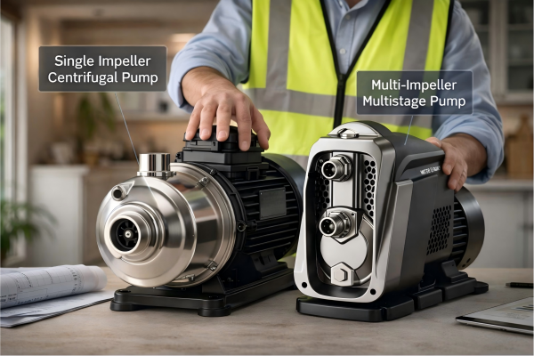
How they work: A submersible pump is a multi-stage centrifugal pump.
It consists of a series of impellers stacked on top of each other.
Each stage adds more pressure, allowing the pump to push water up from extreme depths of hundreds or even thousands of feet.
The pump and its sealed motor are a single unit lowered into the well.
Key features include:
- No priming needed: The pump is already underwater.
- Very quiet operation: The well and ground muffle any noise.
- Highly efficient: Pushing water is more efficient than pulling it.
- More difficult to service: Requires pulling the entire unit out of the well.
Submersible pumps are the standard for any deep well irrigation application.
Variable Speed Drive (VSD) Pumps
Variable Speed Drive (VSD) pumps, also known as variable frequency drive (VFD) pumps, are the most advanced and energy-efficient option.
They are not a different type of pump mechanism, but rather an intelligent control system added to a centrifugal or submersible pump.
How they work: Instead of running at a single, fixed speed, a VSD pump's motor speed can be adjusted.
The drive alters the electrical frequency supplied to the motor.
According to pump affinity laws, reducing a pump's speed by 20% can reduce its energy consumption by nearly 50%.
This is a game-changer for irrigation systems with varying demands, such as:
- Systems with multiple zones of different sizes.
- Drip irrigation where pressure needs to be precisely controlled.
- Applications where a single pump serves both high-flow sprinklers and low-flow drip lines.
A VSD pump can maintain constant pressure even as flow demands change, ensuring every zone gets exactly the right amount of water while using the minimum amount of energy required.
While the initial investment is higher, the energy savings can lead to a return on investment in as little as 1-2 years.
Conclusion
Sizing an irrigation pump correctly comes down to calculating your required flow rate and Total Dynamic Head.
Matching these values to a pump curve ensures efficiency, longevity, and optimal system performance.
FAQs
1. How do you calculate irrigation pump horsepower?
First, calculate the required flow rate (GPM) and Total Dynamic Head (TDH). Then, use the formula: HP = (GPM x TDH) / (3960 x Pump Efficiency) to find the necessary horsepower.
2. What size of pump do I need for a 1-acre garden?
The size depends on the irrigation method. For sprinklers, you might need 20-30 GPM, while drip irrigation might only require 5-10 GPM. Calculate the total flow rate of all emitters.
3. What is the difference between a booster pump and an irrigation pump?
An irrigation pump typically draws water from a source like a well or pond. A booster pump increases the pressure in an existing water line that already has some flow.
4. How many GPM does it take to run an irrigation system?
This varies widely. A small residential system might need 10 GPM, while a large agricultural field could require over 1,000 GPM. It is the sum of all concurrently running sprinklers.
5. Can a pump be too big for an irrigation system?
Yes. An oversized pump operates inefficiently, wastes significant electricity, and can cause high-pressure damage to pipes and fittings through water hammer. It also leads to premature pump failure.
6. How far can a 1 HP pump push water for irrigation?
This depends on the pump's design and the pipe size. A 1 HP pump might push 20 GPM up 100 feet of head, but a different 1 HP model might push 50 GPM up only 40 feet.
7. Does pipe size affect water pressure in irrigation?
Yes, significantly. Smaller pipes create much more friction loss, which reduces the pressure available at the sprinkler heads. Doubling pipe diameter can reduce friction loss by over 75%.
8. How do I choose a solar pump for irrigation?
Calculate your daily water volume requirement and the Total Dynamic Head (TDH). Match this to a solar pump system's specifications, ensuring the solar panel array can power the pump during peak sun hours.