Struggling with inconsistent water pressure in your building?
A booster pump is your solution.
It instantly solves low pressure problems.
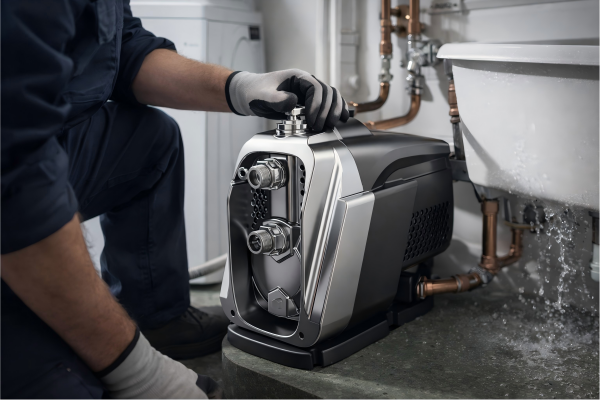
For optimal performance, a booster pump should be installed on the main water line coming into the property.
This placement is typically right after the water meter but before the line splits to feed different fixtures.
This ensures the entire building receives boosted, consistent pressure.

Placing your pump correctly is just the first step.
An incorrectly sized pump, even in the perfect spot, won't solve your pressure problems and might even create new ones.
It can lead to wasted energy, excessive noise, or a pump that fails prematurely.
To truly fix your water pressure issues, you need to match the pump's power to your building's specific needs.
This involves a careful calculation of both the water flow required and the pressure needed to deliver it everywhere.
Understanding this process ensures you select a pump that works efficiently, reliably, and quietly for years.
Let's break down how to properly size your booster pump for the ideal installation.
How do you calculate the required flow rate?
Tired of weak showers when someone else uses a tap?
This is a flow rate problem.
Calculating the correct flow rate prevents pressure drops during peak water usage.
To calculate the flow rate, you must determine your building's peak water demand.
This is done by counting all water fixtures, assigning a "fixture unit" (FU) value to each, summing these values, and then converting the total FUs to gallons per minute (GPM) using a standard chart.
Choosing the right flow rate is the foundation of a successful booster pump system.
It's a common mistake to simply buy a powerful pump, hoping it will solve all pressure issues.
This often leads to oversizing, which wastes electricity and puts unnecessary strain on your entire plumbing system.
A pump that is too small, on the other hand, will fail to deliver adequate pressure when multiple taps are open.
The goal is to find the perfect balance.
You need a pump that can handle your property's busiest moments without being excessively powerful for everyday use.
This precise calculation ensures every tap, from the basement laundry to the top-floor shower, receives sufficient water flow simultaneously.
Step 1: Count Your Water Fixtures
The first step is to create a complete inventory of every point of water use the pump will serve.
Walk through the property and list every single fixture.
This includes common items and those that are easily overlooked.
Be thorough in your count.
A missed fixture can lead to an under-sized pump.
Create a simple table to keep your count organized.
| Fixture Type | Quantity |
|---|---|
| Standard Toilet | 3 |
| Kitchen Sink | 1 |
| Bathroom Sink | 3 |
| Shower Head | 2 |
| Bathtub | 1 |
| Washing Machine | 1 |
| Dishwasher | 1 |
| Outdoor Hose Bib | 2 |
Step 2: Assign Fixture Units (FU)
Not all fixtures use water the same way.
A toilet flush demands a different volume and flow than a kitchen sink.
To standardize this, the plumbing industry uses a value called a "fixture unit" (FU).
Each type of fixture is assigned a specific FU value based on its typical water consumption.
You can find these values in plumbing design handbooks, like the ASPE Design Handbook.
These standards provide a reliable basis for your calculations.
Here is a table with common fixture unit values for private use.
| Fixture Type | Fixture Units (FU) |
|---|---|
| Standard Toilet | 2.5 |
| Kitchen Sink | 1.5 |
| Bathroom Sink | 1.0 |
| Shower Head | 2.0 |
| Bathtub | 4.0 |
| Washing Machine | 4.0 |
| Dishwasher | 1.5 |
| Outdoor Hose Bib | 2.5 |
Step 3: Calculate Total Fixture Units
Now, you combine the data from the first two steps.
Multiply the quantity of each fixture by its assigned FU value.
Then, sum the results to get the total fixture units for the entire building.
This number represents the theoretical maximum water demand of your system.
Using our example:
- Toilets: 3 x 2.5 FU = 7.5 FU
- Kitchen Sink: 1 x 1.5 FU = 1.5 FU
- Bathroom Sinks: 3 x 1.0 FU = 3.0 FU
- Shower Heads: 2 x 2.0 FU = 4.0 FU
- Bathtub: 1 x 4.0 FU = 4.0 FU
- Washing Machine: 1 x 4.0 FU = 4.0 FU
- Dishwasher: 1 x 1.5 FU = 1.5 FU
- Hose Bibs: 2 x 2.5 FU = 5.0 FU
Total Fixture Units = 7.5 + 1.5 + 3.0 + 4.0 + 4.0 + 4.0 + 1.5 + 5.0 = 30.5 FU
Step 4: Convert Fixture Units to Gallons Per Minute (GPM)
The final step is to convert your total FU value into the flow rate, measured in gallons per minute (GPM).
This conversion is not linear.
The probability of all fixtures being used at the exact same time decreases as the number of fixtures increases.
Therefore, you must use a standard conversion chart, often called Hunter's Curve.
This chart translates the total FU into a realistic peak flow rate.
For our example of 30.5 FU, a standard chart would suggest a flow rate of approximately 22-24 GPM.
This is the target flow rate your booster pump must be able to provide.
Remember to add flow for any high-demand systems like irrigation zones or commercial laundry facilities separately if they operate at the same time as other fixtures.
How to Determine the Total Dynamic Head (TDH)?
Worried the pump you choose won't be strong enough to reach the top floor?
Calculating pressure, or head, is the key.
This guarantees your pump has the power to overcome gravity and friction.
Total Dynamic Head (TDH) is the total pressure the pump must create.
It's calculated by adding the vertical lift (static head), pressure lost to pipe friction (friction head), and the required final pressure at the highest tap, then subtracting any existing city pressure.
After determining the flow rate (GPM), calculating the Total Dynamic Head (TDH) is the second critical piece of the puzzle.
TDH is essentially the total workload you are asking the pump to do.
It's measured in feet or meters of head, which can be easily converted to pressure units like PSI or bar.
Getting this number right is non-negotiable.
If you underestimate the TDH, you'll end up with weak flow at the highest or furthest fixtures, defeating the purpose of installing a booster pump.
If you overestimate it, you'll buy a much more powerful and expensive pump than you need, leading to high energy bills and potential damage to your pipes from excessive pressure.
The calculation breaks this total workload down into several distinct components, each accounting for a different force the pump must overcome.
Breaking Down the TDH Calculation
The formula looks complex, but it's a simple sum of pressures.
Total Head = Static Head + Friction Head + Required Pressure - Current Pressure + Safety Margin
Let's examine each part.
Static Head: The Uphill Battle
This is the simplest part to understand.
Static head is the vertical distance, in feet or meters, from the booster pump to the highest point where water will be used.
If your pump is in the basement and the highest shower is on the second floor, you need to measure that vertical height.
For example, if the pump is 5 feet above the basement floor, and the second-floor shower head is 25 feet above the basement floor, the static head is 20 feet (25 ft - 5 ft).
Gravity is always working against your pump, and this value quantifies that force.
Friction Head: The Hidden Resistance
Water doesn't flow through pipes for free.
It loses energy as it rubs against the inside surfaces of pipes and pushes through elbows, valves, and fittings.
This energy loss is called friction head.
Calculating it precisely requires knowing:
- Flow Rate (GPM): Higher flow rates create much more friction.
- Pipe Diameter: Smaller pipes cause significantly more friction than larger ones for the same flow rate.
- Pipe Length: The longer the total pipe run from the pump to the furthest fixture, the more friction loss.
- Pipe Material: Rougher pipes (like old galvanized steel) create more friction than smooth ones (like PVC or copper).
- Fittings: Every 90-degree elbow, valve, and tee adds to the total friction.
You can use friction loss charts to find the head loss per 100 feet of a specific pipe size and flow rate.
Then, add an allowance for fittings (often as an equivalent length of straight pipe).
For a large residential home, friction head can easily add 10 to 30 feet or more to your TDH calculation.
Required Pressure: The User Experience
This is the pressure you want to feel at the tap.
What is the minimum pressure needed for a fixture to operate correctly?
Most modern fixtures, like shower heads and faucets, work best with about 30 to 40 pounds per square inch (PSI) of pressure.
It's crucial to convert this required pressure into feet of head to add it to your other values.
The conversion is simple: 1 PSI = 2.31 feet of head.
So, if you want 40 PSI at your top-floor shower:
Required Pressure = 40 PSI x 2.31 = 92.4 feet of head.
Current Pressure: The Head Start
If you are boosting a municipal water supply, you aren't starting from zero.
The city is already providing some pressure.
You need to measure this incoming pressure at the point where the pump will be installed.
Let's say your city supply provides 25 PSI.
You must subtract this "head start" from your total calculation.
Pressure to Subtract = 25 PSI x 2.31 = 57.75 feet of head.
Safety Margin: The Professional Buffer
Finally, always add a safety margin.
This accounts for factors that are hard to predict.
Pipes can age and become rougher, increasing friction over time.
Your needs might change, or your initial calculations might have slight inaccuracies.
A safety margin of 5 to 10 PSI is standard practice.
Safety Margin = 10 PSI x 2.31 = 23.1 feet of head.
By carefully calculating and adding these five components, you arrive at the Total Dynamic Head.
This figure, along with your GPM, is what you need to select the perfect pump.
How to Select the Perfect Pump?
Overwhelmed by all the pump models and specifications?
Choosing the right pump doesn't have to be a guessing game.
Focus on matching your needs to the pump's performance data.
To select the perfect pump, you use your calculated flow rate (GPM) and Total Dynamic Head (TDH).
You then find the intersection of these two values on a manufacturer's pump performance curve.
The ideal pump will have this point located in the middle of its efficiency range.
You've done the hard work of calculating your exact requirements.
You have the two most important numbers: your required flow rate in GPM and your Total Dynamic Head in feet.
Now, you can move from theoretical calculations to selecting a real piece of hardware.
This final step is about matching your specific GPM and TDH to a manufacturer's certified performance data.
Rushing this step or relying on a salesperson's guess can undo all your careful preparation.
The key tool for this task is the pump performance curve, a graph that is unique to every single pump model.
It's the pump's resume, showing exactly how it performs under different conditions.
Learning to read this chart ensures you choose a pump that is not just adequate, but optimal for your system.
An optimal choice leads to energy efficiency, quiet operation, and a long, reliable service life.
Reading the Pump Performance Curve
A pump curve is a graph with flow rate (GPM or m³/h) on the horizontal axis (X-axis) and head (feet or meters) on the vertical axis (Y-axis).
The curve itself shows the inverse relationship between flow and head.
A pump can deliver high pressure (head) at low flow, or high flow at low pressure (head).
It cannot do both at the same time.
Your job is to find your specific operating point, or "duty point," on that curve.
- Locate your required GPM on the horizontal axis.
- Locate your required TDH on the vertical axis.
- Find the intersection point of these two values on the graph.
The ideal pump model is one where your duty point falls directly on, or very close to, its main performance curve.
Crucially, this point should also land within the pump's Best Efficiency Point (BEP) range, often shown as separate "efficiency islands" or curves on the chart.
Operating at or near the BEP means the pump is running at its most energy-efficient and mechanically sound point.
Beyond the Curve: Core Technology Matters
Simply finding a pump that meets the duty point is not enough for a modern, high-performance system.
The underlying technology of the pump dictates its efficiency, noise level, and intelligence.
This is where advanced systems show their true value.
The Power of VFD + PMSM
Traditional pumps run at a single, fixed speed.
They are either on at 100% power or off.
This is incredibly inefficient because your building's water demand is constantly changing.
A modern solution uses a Variable Frequency Drive (VFD) paired with a Permanent Magnet Synchronous Motor (PMSM).
- Variable Frequency Drive (VFD): This is the brain of the pump. It constantly monitors system pressure. When a tap opens and pressure starts to drop, the VFD instantly increases the motor's speed just enough to maintain the target pressure. When the tap closes, it slows the motor down. This "soft start" and "soft stop" functionality dramatically reduces electrical consumption and eliminates water hammer, a destructive pressure surge that can damage pipes and appliances.
- Permanent Magnet Synchronous Motor (PMSM): This is the muscle. Compared to traditional asynchronous motors, PMSM technology is significantly more energy-efficient, runs much cooler, and operates at near-silent levels (often below 50dB). Their ability to maintain torque at various speeds makes them perfect partners for a VFD controller.
This combination ensures a constant, unwavering pressure at every faucet, regardless of how many are in use, all while using up to 50% less energy than a conventional pump.
Uncompromising Durability and Protection
A booster pump is a long-term investment.
Its construction and built-in protections are what separate a professional-grade unit from a consumer-grade one that will fail in a few years.
Key features to demand include:
- Sealed Electronics (IP67): The VFD controller is the most sensitive part. Look for units where the main Printed Circuit Board (PCB) is fully potted or sealed in a waterproof compound. This protects it from moisture, dust, and condensation, which are the leading causes of electronic failure in pumps. This single feature can extend the controller's life by years.
- Premium Materials: The parts touching water must resist corrosion. An AISI304 stainless steel impeller and pump body are the standard for clean water applications, ensuring durability and water safety. The motor housing should be robust and designed for excellent heat dissipation to prolong motor life.
- Comprehensive Safety Protections: An intelligent pump protects itself. A complete system should include a suite of automated protections. This "14-Shield" system is a good example of what to look for, safeguarding against common issues that would destroy lesser pumps.
| Protection Type | Function |
|---|---|
| Electrical | Over/under voltage, overcurrent, phase loss |
| Thermal | Motor overheat, VFD overheat, high water temp |
| System | Dry run (water shortage), pipeline leak, anti-freeze |
| Sensor | Self-diagnosis for pressure and temperature sensor failure |
These intelligent protections turn the pump from a simple motor into a self-sustaining, resilient system manager, providing peace of mind and dramatically reducing service calls.
Conclusion
Properly installing and sizing a booster pump transforms an inconsistent water supply into a reliable, high-performance system.
It ensures client satisfaction and reinforces your reputation for quality and expertise.
FAQs
What is the best location for a booster pump?
The best location is on the main water line after the water meter and any filtration systems, but before the line branches off to individual fixtures.
Can a booster pump be too powerful?
Yes.
An oversized pump can cause excessive pressure, leading to pipe strain, leaks, water hammer, and high energy consumption.
Proper sizing is crucial.
Do I need a booster pump if I have city water?
You might.
If your city pressure is low due to high elevation, distance from the main line, or an old municipal system, a booster pump is needed.
How much pressure should a booster pump add?
It should add enough pressure to overcome height (static head) and pipe friction, and still provide 30-50 PSI at the highest fixture.
Are VFD booster pumps quiet?
Yes, modern VFD pumps, especially those with Permanent Magnet motors, are extremely quiet, often operating at levels below 50 decibels, which is quieter than a library.
Can a booster pump run continuously?
A fixed-speed pump running continuously indicates a major leak or that it's undersized.
A VFD pump will run continuously at varying speeds to match demand.
What maintenance does a booster pump require?
Modern, high-quality pumps require very little maintenance.
Periodically check for leaks, listen for unusual noises, and ensure intake filters (if any) are clean.
Will a booster pump increase my electric bill?
A traditional, fixed-speed pump will.
However, an energy-efficient VFD booster pump can actually reduce overall energy use by up to 50% by only running as fast as needed.