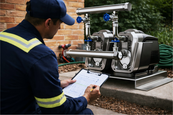
Is your pump failing to deliver the pressure you need?
This inefficiency can disrupt your entire operation, leading to costly downtime and lost productivity.
Understanding the root causes is the first step.
A centrifugal pump can lose pressure for several critical reasons. These include air leaks in the suction line, blockages in pipes or filters, and cavitation. Other major factors are incorrect pump speed (RPM), significant wear on the impeller or casing, and a system design that mismatches the pump's capabilities.
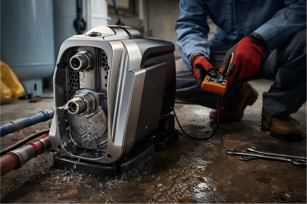
Diagnosing low pressure in a centrifugal pump can feel overwhelming.
You might check one thing, only to find the problem lies elsewhere.
This wastes valuable time and resources.
But a systematic approach can simplify this process significantly.
By breaking down the potential issues into manageable categories, you can pinpoint the exact cause of pressure loss efficiently.
This guide will walk you through the most common culprits, from simple blockages to complex system-wide problems.
Let's dive into the specifics so you can restore your pump's performance and get your system back to peak efficiency.
How Do Leaks and Blockages Affect Pump Pressure?
Are you struggling with inconsistent pump output?
Air leaks and physical blockages are common culprits that secretly sabotage your system's pressure, making diagnosis difficult.
Identifying them is key.
Air leaks on the suction side introduce air into the pump, which is far less dense than liquid. The pump wastes energy compressing this air instead of moving fluid, causing a dramatic pressure drop. Blockages create high friction loss, demanding more energy to push fluid through, which also reduces the final discharge pressure.
A small leak or a partial blockage might not seem like a major issue at first.
But their impact on pump performance is significant and can worsen over time.
These problems are often the first place to look when troubleshooting low pressure because they are both common and relatively straightforward to fix once identified.
Understanding how each one specifically degrades pressure helps in creating a targeted diagnostic plan.
Diagnosing Suction Side Air Leaks
Air is the enemy of a centrifugal pump.
Even a tiny leak in the suction line can allow a surprising amount of air to enter the system.
A pump designed for liquid cannot efficiently handle this air-liquid mixture.
This condition is often called "losing prime."
The pump's impeller spins, but it's hitting air pockets instead of a solid column of water.
This leads to a reported pressure loss of up to 70% or more, depending on the volume of air ingress.
You might hear unusual noises, like gravel rattling inside the pump, as air bubbles collapse.
Visual inspection is the first step.
- Check all joints, flanges, and valve stems on the suction side.
- Look for worn gaskets or cracked piping.
- Apply a shaving cream or soap solution to suspected leak points; if there's a leak, the vacuum will pull the solution into the pipe, revealing the location.
Locating and Clearing Blockages
Blockages act like a bottleneck in your system.
They restrict flow and create excessive friction loss.
This means the energy the pump imparts to the fluid is wasted overcoming the obstruction, leaving less energy available to generate pressure at the discharge point.
Common blockage locations include:
| Blockage Location | Common Cause | Impact on System |
|---|---|---|
| Suction Strainer/Filter | Debris, sediment, scale buildup | Starves the pump of fluid, can lead to cavitation. |
| Impeller Vanes | Stringy material, solids, rags | Reduces impeller efficiency, causes imbalance and vibration. |
| Check Valves | Stuck in a partially closed position | Creates a permanent, significant restriction in the line. |
| Piping Elbows | Sedimentation buildup over time | Gradually increases system friction and reduces flow. |
A simple way to check for blockages is to compare pressure gauge readings.
Install gauges before and after components like filters and valves.
A significant pressure drop across a component indicates a likely restriction.
For instance, a new filter might have a 1-2 PSI drop, but a clogged one could show a drop of 10-15 PSI, directly subtracting from your final system pressure.
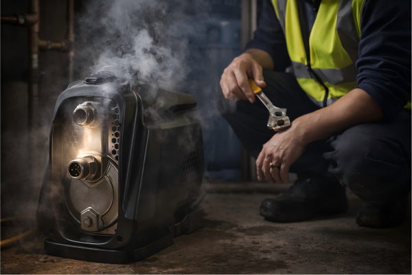
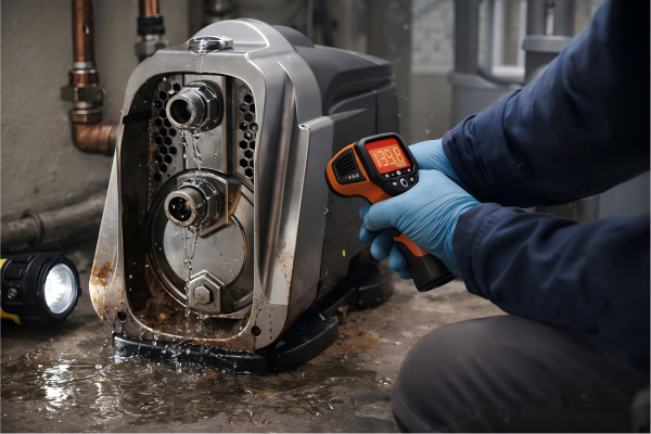
Is Cavitation the Silent Killer of Your Pump's Performance?
Does your pump sound like it's pumping gravel?
That noise is often cavitation, a destructive process that severely erodes pump components and cripples its pressure output.
Ignoring it leads to failure.
Cavitation occurs when the pressure inside the pump drops below the liquid's vapor pressure, causing vapor bubbles to form. These bubbles collapse violently when they reach a higher-pressure zone, creating shockwaves that erode the impeller and casing. This damage degrades hydraulic performance, causing a significant loss of pressure.
Cavitation is more than just a noisy inconvenience.
It is a direct assault on the heart of your pump.
Each bubble collapse acts like a tiny hammer blow against the impeller's surface.
Over time, this process, known as "pitting," physically removes metal from the impeller, altering its hydraulic shape and drastically reducing its ability to impart energy to the fluid.
The result is a pump that can no longer meet its designed performance curve.
Understanding the conditions that lead to cavitation is crucial for prevention and diagnosis.
Understanding NPSH (Net Positive Suction Head)
The concept of Net Positive Suction Head is fundamental to preventing cavitation.
There are two types of NPSH:
- NPSHa (Available): This is a characteristic of your system. It's the absolute pressure at the pump suction inlet, minus the liquid's vapor pressure. It represents the pressure available to prevent the liquid from vaporizing.
- NPSHr (Required): This is a characteristic of the pump, provided by the manufacturer. It is the minimum pressure required at the suction inlet to prevent cavitation.
Cavitation is a certainty when NPSHa < NPSHr.
To avoid cavitation, you must always ensure your system provides more available head than the pump requires.
A safety margin of at least 3-5 feet (or 1-1.5 meters) of NPSHa above the NPSHr is a standard industry recommendation.
Common Causes of Low NPSHa
Several system factors can reduce your NPSHa, pushing the pump into a state of cavitation.
Identifying these factors is key to resolving the issue.
| Factor | Description | Solution |
|---|---|---|
| High Liquid Temperature | As temperature rises, vapor pressure increases, which directly reduces NPSHa. A 20°F (11°C) rise in water temperature can increase vapor pressure by over 50%. | Lower the liquid temperature, or select a pump designed for higher temperatures. |
| Blocked Suction Line | A clogged filter or pipe increases friction loss on the suction side, effectively lowering the pressure at the pump inlet. | Regularly clean all suction-side filters and inspect piping for obstructions. |
| Pump Running Too Far Right on Curve | Operating the pump at a much higher flow rate than its Best Efficiency Point (BEP) increases the velocity of the fluid, causing a pressure drop at the impeller eye. | Install a throttle valve on the discharge side to reduce flow and move the operating point back towards the BEP. |
| High Suction Lift | The vertical distance the pump has to pull the liquid is too great, reducing the static pressure at the inlet. | Lower the pump's position relative to the liquid source or raise the liquid level. |
By addressing these system issues, you can increase the NPSHa and eliminate the destructive force of cavitation, restoring pressure and extending the pump's service life.
Could Incorrect Pump Speed Be the Culprit?
Is your pump's performance falling short of expectations?
You might assume a mechanical fault, but the issue could be as simple as the pump's rotational speed.
An incorrect speed directly impacts pressure.
According to the Pump Affinity Laws, the pressure (or head) a centrifugal pump generates is directly proportional to the square of its speed change. This means even a small reduction in rotational speed (RPM) results in a much larger drop in discharge pressure. For example, a 10% decrease in speed causes a 19% pressure loss.
The relationship between speed and pressure is not linear; it's exponential.
This is a critical concept that is often overlooked during initial troubleshooting.
Many operators focus on leaks or blockages while the root cause is hidden in the motor's performance or the drive's settings.
Whether you are using a fixed-speed motor or a Variable Frequency Drive (VFD), verifying the actual operating speed is a vital diagnostic step.
A mismatch between the required speed and the actual speed will guarantee the pump cannot meet its performance specifications.
The Role of Variable Frequency Drives (VFDs)
VFDs offer fantastic energy savings and process control by allowing you to adjust the motor's speed.
However, an incorrect setting is a common source of low-pressure problems.
A VFD that is programmed to run at 50 Hz instead of the required 60 Hz will reduce the pump speed by about 17%.
According to the affinity laws, this speed reduction will cause a pressure drop of approximately 31%.
Here's how to check:
- Verify VFD Parameters: Check the HMI or programming interface of the VFD. Ensure the commanded frequency (e.g., 60 Hz) matches the system's requirement for the desired pressure.
- Check for Speed Limits: Some VFDs have maximum speed/frequency limits programmed in for safety or process reasons. Ensure this limit isn't set too low.
- Measure Actual Motor Speed: Use a handheld tachometer to measure the actual shaft RPM. Compare this to the speed the VFD is supposed to be commanding. Discrepancies could point to a problem with the VFD or the motor itself.
Issues with Fixed-Speed Motors
While simpler, fixed-speed motors can also be a source of incorrect speed.
You can't adjust their speed, but you can ensure you have the correct motor installed and that it's receiving proper power.
| Problem | Symptom | How to Diagnose |
|---|---|---|
| Incorrect Motor Poling | A 4-pole motor runs at ~1800 RPM (on a 60Hz supply), while a 2-pole motor runs at ~3600 RPM. Installing a 4-pole motor where a 2-pole is required will cut the speed in half, reducing pressure by 75%. | Check the motor's nameplate. The listed RPM should match the pump's design specifications. |
| Voltage Imbalance/Drop | An unstable or low voltage supply can cause an induction motor to "slip" more, resulting in a lower operating RPM than its nameplate rating. A significant voltage drop under load can cause a 3-5% speed reduction. | Use a multimeter to measure the voltage at the motor terminals while the pump is running under load. Compare this to the nameplate voltage. |
| Wrong Frequency Supply | Running a motor designed for a 60 Hz supply on a 50 Hz supply (or vice versa) without adjustments will directly alter its speed by about 17%. | Confirm the frequency of your power supply matches the motor's nameplate specifications. |
Ensuring the pump is driven at the correct, stable speed is fundamental.
Correcting a speed-related issue can often restore full pressure without ever needing to disassemble the pump.
Why Does Impeller Wear Drastically Reduce Pressure?
Has your pump's pressure slowly faded over months or years?
This gradual decline often points directly to internal wear, specifically of the impeller.
Its condition is critical for performance.
The impeller's job is to transfer energy from the motor to the fluid. As the impeller vanes wear down from abrasion or corrosion, their ability to accelerate the fluid diminishes. This reduces the velocity imparted to the water, which directly translates into a lower discharge pressure. Even a 5% trim or wear on the impeller's diameter can reduce pressure by 10%.
Think of the impeller as the heart of the pump.
Its precise geometry is engineered to move liquid efficiently.
Any deviation from this design, whether from erosion, corrosion, or cavitation damage, compromises its function.
Wear is not always uniform.
It can affect the vane tips, the surface of the volute, or the clearance between the impeller and the casing.
Each type of wear contributes to a loss of hydraulic efficiency and, consequently, a drop in pressure.
This is why a pump that once performed perfectly may struggle to meet demand after thousands of hours of operation.
The Impact of Impeller Diameter
The diameter of the impeller is one of the most critical factors determining a pump's pressure output.
The Pump Affinity Laws state that head (pressure) is proportional to the square of the impeller diameter.
This means a small change has a big effect.
- Trimming: Impellers are sometimes intentionally "trimmed" or machined to a smaller diameter to meet a specific duty point. If a pump is retrofitted with an impeller that was trimmed too much for the application, it will never reach the desired pressure.
- Abrasive Wear: When pumping liquids with suspended solids (like sand or sludge), the particles act like sandpaper on the impeller's outer edge. This abrasive action slowly reduces the effective diameter of the impeller over time. A pump in a mining application might lose 10% of its pressure capability in just 1,000-2,000 hours of service due to this type of wear.
Wear Rings and Internal Clearances
To maximize efficiency, the clearance between the rotating impeller and the stationary pump casing must be very tight.
This prevents high-pressure liquid from leaking back to the low-pressure suction side.
Many pumps use replaceable "wear rings" to maintain this critical tolerance.
| Component | Function | Effect of Wear |
|---|---|---|
| Wear Rings | Provide a small, renewable clearance between the impeller and casing to limit internal recirculation. | As wear rings erode, the clearance gap widens. This allows more fluid to slip from the discharge side back to the suction side. This internal leakage can account for a 15-20% loss in pressure and flow in a severely worn pump. |
| Impeller Vanes | Accelerate the fluid radially outward to build velocity and pressure. | Vanes thinned by corrosion or eroded by cavitation cannot effectively grip and accelerate the fluid. The hydraulic efficiency drops, and so does the pressure. |
| Volute/Casing | The volute is the spiral-shaped casing that collects the fluid from the impeller and converts its high velocity into high pressure. | Wear or pitting inside the volute disrupts the smooth flow of liquid. This turbulence creates energy losses and prevents the efficient conversion of velocity to pressure. |
An internal inspection is often necessary to diagnose these issues.
Measuring the impeller diameter and the clearance at the wear rings against the manufacturer's specifications will provide a definitive answer on whether internal wear is the cause of your pressure loss.
What Role Does System Design Play in Pressure Loss?
Is your brand-new pump underperforming from day one?
The problem might not be the pump itself, but the system it's connected to.
A poorly designed system can prevent any pump from reaching its potential.
System resistance, or "system head," is the total pressure the pump must overcome to move fluid. If the actual system head is higher than what the pump was selected for, the pump will operate at a lower flow rate and may not achieve the desired pressure at the point of use. This mismatch is a common design flaw.
A pump does not create pressure on its own.
It provides flow against the resistance it encounters.
This resistance comes from two sources: the static height the water needs to be lifted (static head) and the friction created by the pipes, valves, and fittings (friction head).
If the system's total resistance curve intersects the pump's performance curve at a point that doesn't meet your requirements, you will experience "pressure loss."
This isn't a mechanical failure but a fundamental mismatch between the pump's capability and the system's demand.
This is a critical consideration for importers like Andrew, who must ensure the pumps they source are correctly matched to their customers' end-use applications.
Calculating System Head vs. Pump Curve
The first step is to understand the two competing curves.
- Pump Curve: This graph, provided by the manufacturer (like RAFSUN), shows the pressure (head) the pump can deliver at various flow rates. It typically slopes downwards; as flow increases, pressure decreases.
- System Curve: This curve represents your piping system. It starts at the static head (the vertical lift required) and curves upwards as flow increases, because friction losses increase with the square of the flow rate.
The actual operating point of the pump will be the single point where these two curves intersect.
If this point is at a lower pressure than you need, you have a system design problem.
For example, a system with a 20-meter static lift and high friction might require 35 meters of total head at the desired flow.
If the selected pump can only provide 30 meters of head at that flow rate, it will never meet the pressure requirement.
Common System Design Flaws
Several common design choices can unintentionally create excessive system resistance.
| Design Flaw | Description | Consequence |
|---|---|---|
| Undersized Piping | Using pipes with a smaller diameter than recommended for the flow rate dramatically increases fluid velocity and friction loss. Doubling the flow in a pipe can quadruple the friction loss. | The system head curve becomes much steeper, forcing the pump to operate at a higher pressure but a lower flow rate. Usable pressure at the endpoint drops significantly. |
| Excessive Bends and Fittings | Every 90-degree elbow, valve, and reducer adds to the total friction. A complex pipe run with many turns can have far more friction than a straight pipe of the same length. | Each fitting adds "equivalent length" to the pipe run, increasing the total friction head the pump must overcome. |
| Incorrect Valve Selection | Using a globe valve for throttling when a gate valve (for on/off) is in place can add significant, permanent restriction to the system, even when fully open. | The valve itself becomes a major point of pressure loss, robbing the system of performance. |
| High Point in Discharge Line | If the discharge piping goes up and then down, the pump must have enough energy to lift the fluid to the highest point. This can lead to issues with siphoning or air pockets. | The pump must overcome the highest elevation, even if the final discharge point is lower. This increases the required static head. |
A proper system analysis, either through manual calculation or software, is essential before selecting a pump.
Providing your pump supplier with accurate system details—pipe sizes, lengths, lift height, and number of fittings—is crucial to ensure they can recommend a pump that will perform correctly from day one.
Conclusion
Low pump pressure stems from a few key issues.
It can be caused by air leaks, blockages, cavitation, wrong speeds, or internal wear.
System design is also crucial.
FAQs
How do I test my centrifugal pump for pressure?
Attach a calibrated pressure gauge to the pump's discharge port.
Run the pump with the discharge valve closed to read the shut-off head, then open the valve to measure pressure at your normal flow.
What is the fastest way to check for a pressure problem?
First, check the pressure gauges on both the suction and discharge sides.
A very low or fluctuating suction reading points to a blockage or air leak, while a low discharge reading suggests broader issues.
Can a centrifugal pump run without pressure?
No, a pump running without creating pressure indicates a serious problem.
This condition, known as running "dead-headed" (with no flow) or losing prime, can quickly lead to overheating and severe damage.
Why is my pump running but not pumping water?
This is typically due to a loss of prime.
The casing is filled with air instead of water, and the impeller cannot create a vacuum to draw more water in.
Check for air leaks or a failed foot valve.
How does viscosity affect centrifugal pump pressure?
Higher viscosity fluids create more friction.
This increases the system head and may require more power.
The pump's performance will "de-rate," resulting in lower flow and pressure than what is shown on its water-based curve.
What happens if a centrifugal pump runs in reverse?
Running in reverse will cause the pump to operate very inefficiently.
It will produce some flow and pressure, but typically less than 50% of its design capability, and it will draw excessive power.
How often should I inspect my pump for wear?
For clean water applications, a visual inspection every 1-2 years may be sufficient.
For abrasive or corrosive services, inspections should be scheduled every 6-12 months to check impeller and wear ring clearances.
Can I increase pump pressure by changing the motor?
Yes, if you replace the motor with one that has a higher RPM (e.g., swapping a 4-pole for a 2-pole motor).
However, this will significantly increase power draw and must not exceed the pump's maximum allowable speed rating.