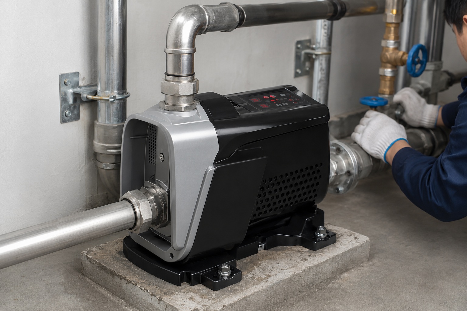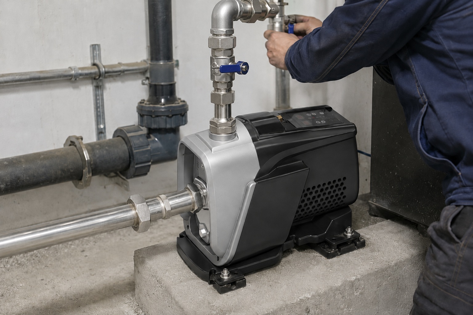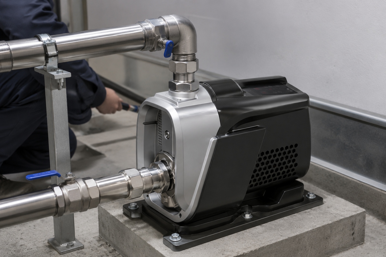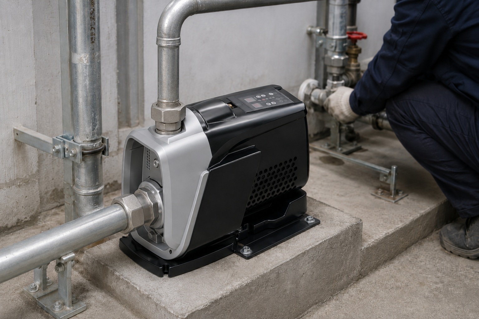
Struggling with inefficient fluid transfer in your operations?
This inefficiency costs you time and money every day.
Improper pump selection can lead to system failure.
A centrifugal pump uses a rotating impeller to increase fluid velocity. It converts this kinetic energy into pressure. This process moves liquid from the inlet to the outlet efficiently. The pump's casing, or volute, is specially designed to manage this energy conversion and direct the flow.
Understanding this elegant process is key to optimizing your fluid systems.
It allows you to select, operate, and maintain your equipment for peak performance.
Let's explore the essential parts that make this technology possible.
You will see how each component plays a critical role in its function.
What Are the Core Components of a Centrifugal Pump?
Confused by complex pump diagrams filled with jargon?
Technical spec sheets can be overwhelming for non-engineers.
This makes choosing the right pump a difficult and risky decision.
The main components are the impeller, the casing (volute), and the shaft. The impeller is the rotating part that imparts energy. The casing directs the fluid flow. The shaft connects the impeller to the motor, providing the necessary rotational power.
Each part of a centrifugal pump is engineered for a specific purpose.
They work together in a synchronized mechanical ballet.
Understanding these individual roles is the first step to mastering pump technology.
This knowledge empowers you to make better procurement and maintenance decisions.
Let's break down the function of each primary component in more detail.
The Impeller: The Heart of the Pump
The impeller is arguably the most critical component.
It is responsible for transferring energy from the motor to the fluid.
It does this by accelerating the liquid outwards from the center of rotation.
Think of it as the engine of the pump.
Its design directly impacts the pump's efficiency and performance characteristics.
Impellers come in several designs, each suited for different applications.
Impeller Types and Their Applications
Choosing the right impeller is crucial for system efficiency.
An incorrect choice can lead to reduced flow, pressure issues, or even pump damage.
Over 30% of premature pump failures can be traced back to misapplication, often involving the wrong impeller type.
| Impeller Type | Description | Best Applications |
|---|---|---|
| Open | Vanes are free on both sides, without shrouds. | Liquids with suspended solids, slurry, wastewater. |
| Semi-Open | Vanes are free on one side and enclosed on the other. | Liquids with some small solids, pulp, paper stock. |
| Closed | Vanes are located between two shrouds. | Clean liquids like water, light oils, chemicals. |
A closed impeller is the most common type used in household booster pumps and clean water applications.
It offers the highest efficiency, often exceeding 85%, because it minimizes leakage and recirculation within the pump.
For applications involving solids, like in wastewater treatment, an open impeller is necessary to prevent clogging, even though its efficiency is lower.
The Casing (Volute): The Energy Converter
The casing, or volute, performs two vital functions.
First, it contains the liquid within the pump.
Second, it converts the kinetic energy of the fluid into pressure.
The impeller throws the liquid out at high velocity.
The volute is a funnel-shaped casing that increases in area as it approaches the discharge outlet.
This gradual expansion slows the fluid down.
According to Bernoulli's principle, as the fluid's velocity decreases, its pressure must increase.
This pressure is what drives the liquid through the piping system.
A well-designed volute can increase a pump's overall efficiency by 5-10%.
It carefully manages the energy conversion process to minimize turbulence and energy loss.
How Does the Pumping Process Actually Happen Step-by-Step?
Is the exact mechanical process inside a pump a mystery?
Visualizing fluid dynamics can be difficult without a clear explanation.
This lack of understanding can hinder effective troubleshooting and maintenance.
First, the prime mover (motor) rotates the shaft and impeller. This rotation creates a low-pressure area at the impeller's center (the eye). Atmospheric pressure pushes liquid into the pump's inlet to fill this void, starting the continuous flow process.
The process of moving fluid with a centrifugal pump is a continuous cycle.
It is a marvel of fluid dynamics engineering.
Let's walk through the journey of a single water molecule as it passes through the pump.
This will clarify each stage of the operation.
From the quiet suction inlet to the high-pressure discharge outlet.
Step 1: Priming and Suction
A centrifugal pump cannot pump air effectively.
Therefore, the pump casing must first be filled with liquid.
This initial step is called priming.
Once primed, the motor can be started.
The impeller begins to rotate at high speed, typically between 1,500 to 3,600 RPM.
The rotating vanes throw the liquid already inside the casing outwards due to centrifugal force.
This action creates a partial vacuum, or a zone of low pressure, at the center of the impeller, known as the impeller eye.
The higher atmospheric pressure on the surface of the liquid in the suction tank or reservoir then pushes the liquid up the suction pipe and into the pump.
This is how the pump continuously draws fluid in.
A failure to prime is the cause of over 40% of initial startup problems.
Step 2: Energy Transfer at the Impeller
As the liquid enters the impeller eye, it is caught by the rotating vanes.
The vanes guide the liquid and force it to rotate with the impeller.
This is where the magic happens.
The motor's mechanical energy is transferred to the liquid in the form of kinetic energy (velocity).
The liquid accelerates radially outward at high speed.
The shape, size, and speed of the impeller determine how much energy is transferred.
A larger diameter impeller or a higher rotational speed will impart more energy, resulting in higher pressure and flow.
Step 3: Energy Conversion in the Volute
The high-velocity liquid exits the tips of the impeller.
It then enters the specially shaped chamber of the volute casing.
The volute is designed to have a progressively increasing cross-sectional area.
As the liquid flows through this expanding area, its velocity gradually decreases.
This reduction in kinetic energy is converted into potential energy, or pressure.
This is the final stage of the process inside the pump.
The high-pressure liquid is then directed out of the pump's discharge nozzle and into the system's piping.
This entire cycle, from suction to discharge, happens almost instantaneously and continues as long as the pump is running and there is liquid to be pumped.
The process is remarkably simple yet highly effective for moving vast quantities of fluid.
What Are the Different Types of Centrifugal Pumps?
Overwhelmed by the sheer variety of pumps on the market?
Choosing the wrong type can lead to poor performance and high energy bills.
This decision paralysis can delay projects and lead to costly mistakes.
Centrifugal pumps are classified by flow type (radial, axial, mixed), number of stages (single-stage, multi-stage), or specific design features (submersible, vertical). Each design is optimized for different pressure, flow rate, and application requirements.
The world of centrifugal pumps is vast and diverse.
However, we can classify them into logical groups based on their design and function.
This helps engineers and distributors select the perfect pump for a specific job.
Understanding these categories is crucial for sourcing the right equipment.
Let's explore the most common classifications you will encounter.
Classification by Number of Stages
The number of impellers a pump has determines its "stages".
This is a primary way to categorize these machines.
-
Single-Stage Pumps: These pumps have only one impeller. They are the most common type. They are ideal for low-pressure, high-flow-rate applications. Their simple design makes them reliable, cost-effective, and easy to maintain. Most residential water booster pumps are single-stage.
-
Multi-Stage Pumps: These pumps have two or more impellers within the same casing. The fluid is passed from the outlet of one impeller to the inlet of the next one in series. Each stage adds more pressure to the fluid. This makes them perfect for high-pressure applications, like boiler feed water, reverse osmosis, and moving water up tall buildings. A four-stage pump can generate roughly four times the pressure of a comparable single-stage pump.
Classification by Casing Design
The design of the pump casing also provides a key classification.
The two main types are volute and diffuser.
-
Volute Casing Pumps: As discussed earlier, these use a spiral-shaped volute to convert velocity to pressure. They are simpler in design and are very common in general service applications.
-
Diffuser Casing Pumps (Turbine Pumps): These pumps have stationary diffuser vanes surrounding the impeller. These vanes provide a more controlled and efficient path for the fluid to slow down, converting velocity to pressure with higher efficiency. They are typically used in high-performance applications where efficiency is paramount. Diffuser pumps can achieve efficiencies 2-4% higher than volute pumps in optimal conditions.
Classification by Specific Application
Pumps are often named after their intended use or placement.
This is the most practical way to categorize them for specific industries.
| Pump Type | Primary Use Case | Key Feature |
|---|---|---|
| Submersible Pump | Draining wells, boreholes, submerged sumps | The motor is hermetically sealed and close-coupled to the pump body. The entire assembly is submerged in the fluid to be pumped. |
| Booster Pump | Increasing pressure in water systems | Typically a single or multi-stage pump designed to "boost" existing pressure from a municipal supply or storage tank. |
| Vertical Pump | Space-saving industrial applications, deep wells | The pump shaft is oriented vertically. This design minimizes the floor space required for installation. |
| Solar Water Pump | Off-grid water supply for irrigation or livestock | Powered directly by photovoltaic (PV) panels. Often incorporates a permanent magnet motor and VFD for high efficiency with variable power. |
This application-based naming helps buyers quickly identify the right type of product for their needs.
It matches a specific problem with a proven engineering solution.
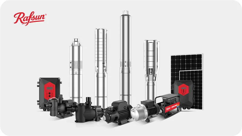
RAFSUN specializes in several of these categories, including VSD booster pumps, solar pumps, and deep well pumps, offering patented technology for superior performance.
Conclusion
In summary, centrifugal pumps convert rotational energy into fluid pressure.
This efficient process relies on the impeller and casing.
Understanding this helps choose the right pump.
FAQs
What is the main principle of a centrifugal pump?
Its main principle is converting rotational energy from a motor into an increase in fluid pressure. This is achieved by accelerating the fluid with a spinning impeller.
What are the two main parts of a centrifugal pump?
The two primary parts are the rotating impeller, which imparts velocity to the fluid, and the stationary casing (volute), which converts that velocity into pressure.
Can a centrifugal pump run without water?
No, running a centrifugal pump dry will cause severe damage. The pumped fluid is essential for cooling and lubrication of the pump's internal seals and bearings.
What is pump head and flow rate?
Head is the height to which a pump can raise a fluid, measured in meters or feet. Flow rate is the volume of liquid a pump can move per unit of time.
What is priming a centrifugal pump?
Priming is the process of filling the pump casing with liquid before it is started. This is necessary because centrifugal pumps cannot effectively pump air or vapor.
How do I choose a centrifugal pump?
Choose a pump based on your required flow rate, head (pressure), the type of fluid being pumped, and the available power source. Always consult a pump performance curve.
Why is my centrifugal pump not building pressure?
Common causes include the pump not being properly primed, a leak in the suction line, a clogged impeller, or the pump running in the wrong direction.
What is cavitation in a pump?
Cavitation is the formation and collapse of vapor bubbles inside a pump. It occurs when suction pressure is too low and can cause significant damage and noise.