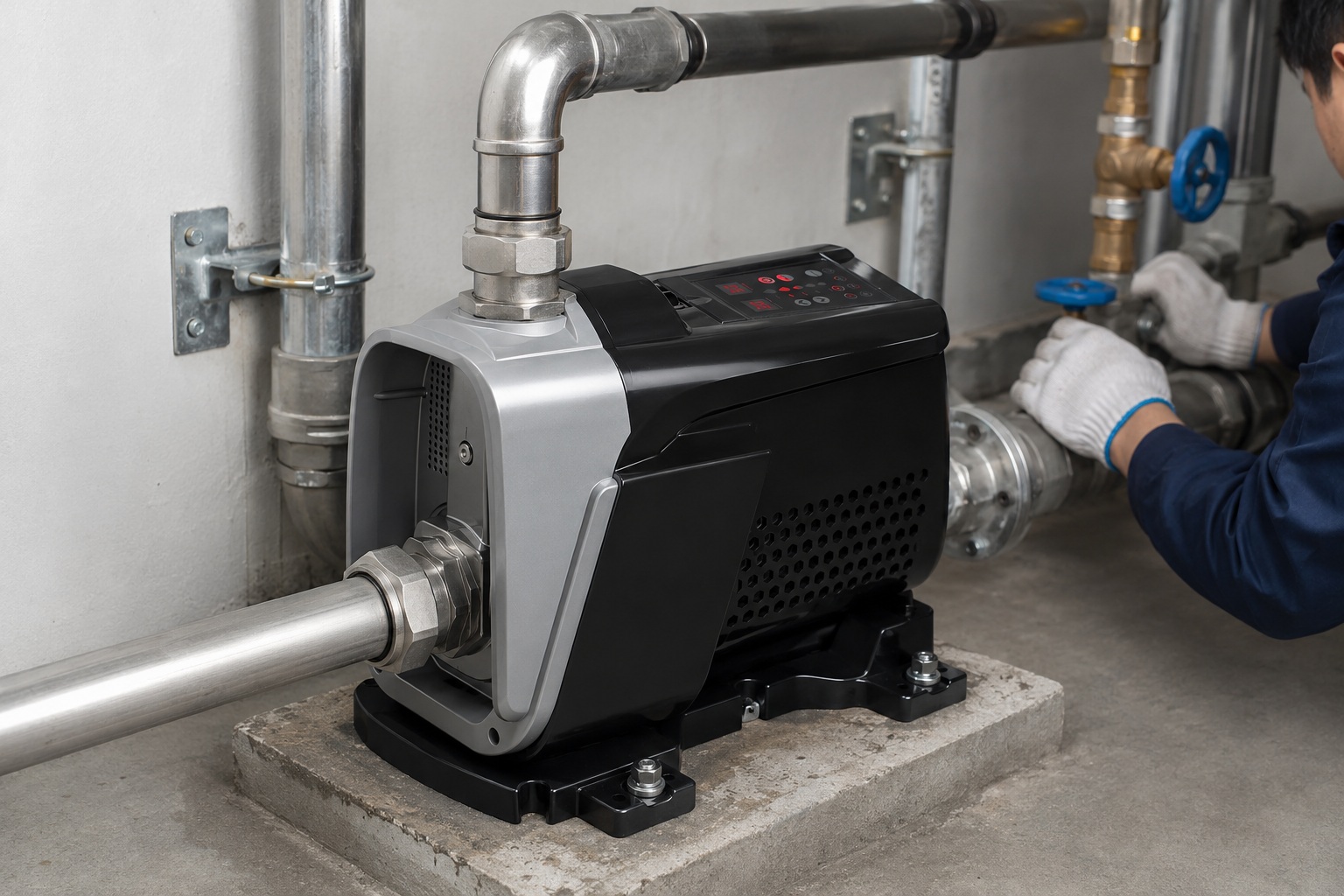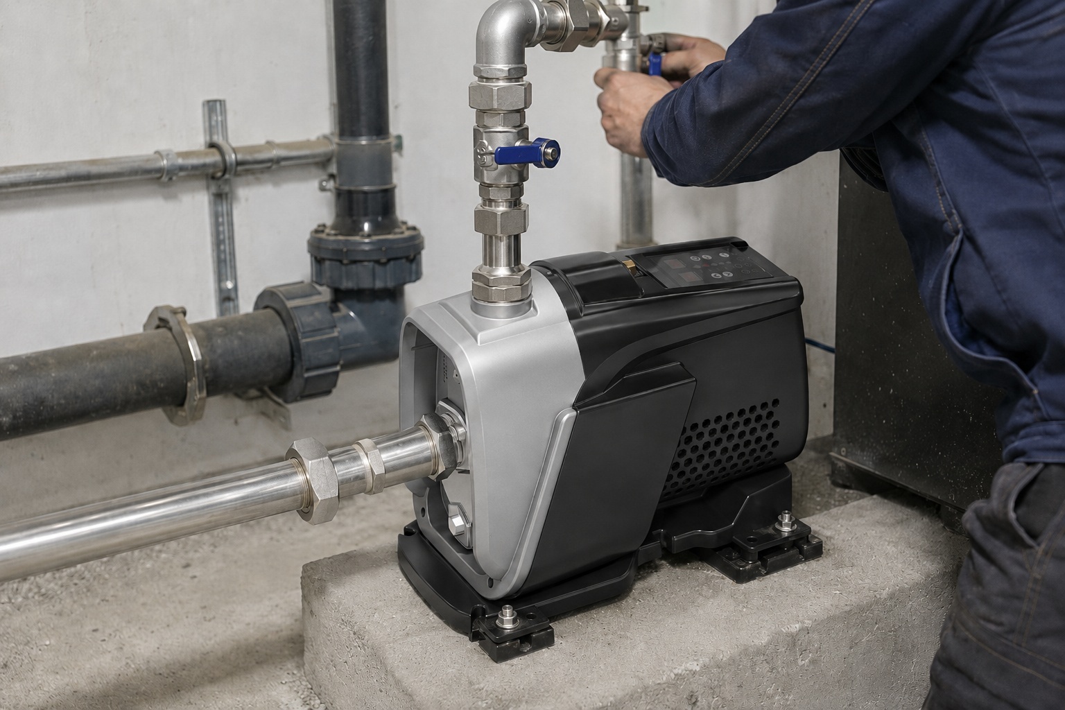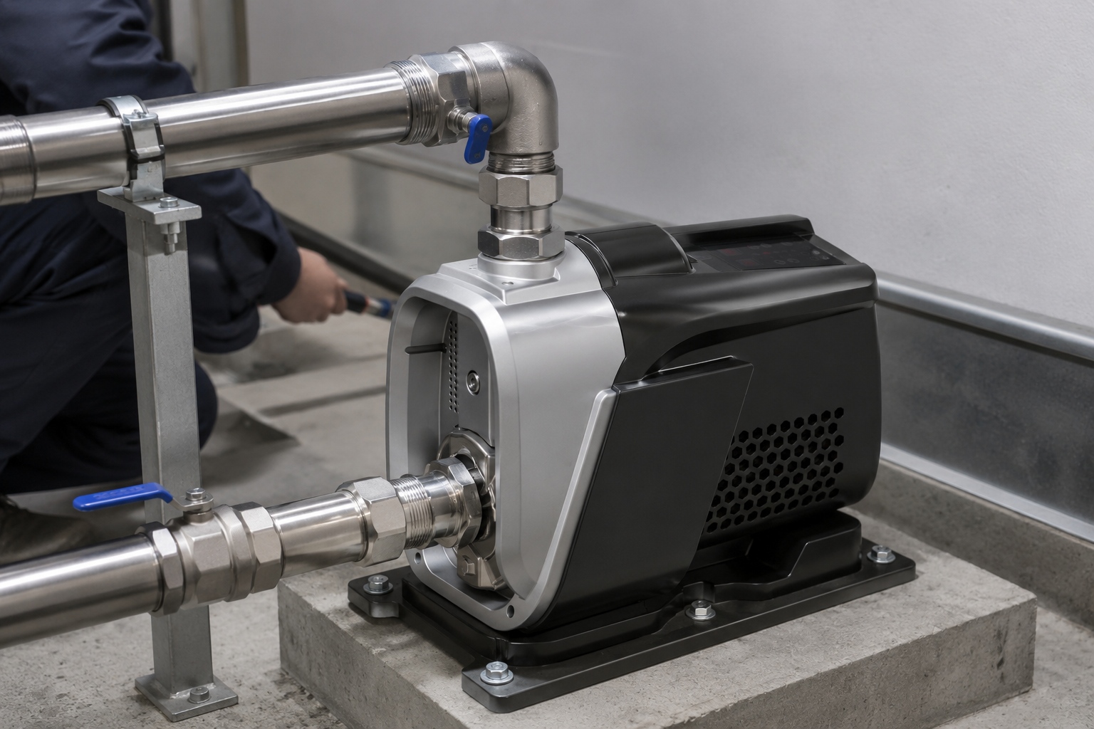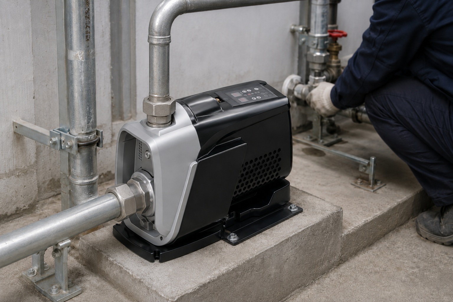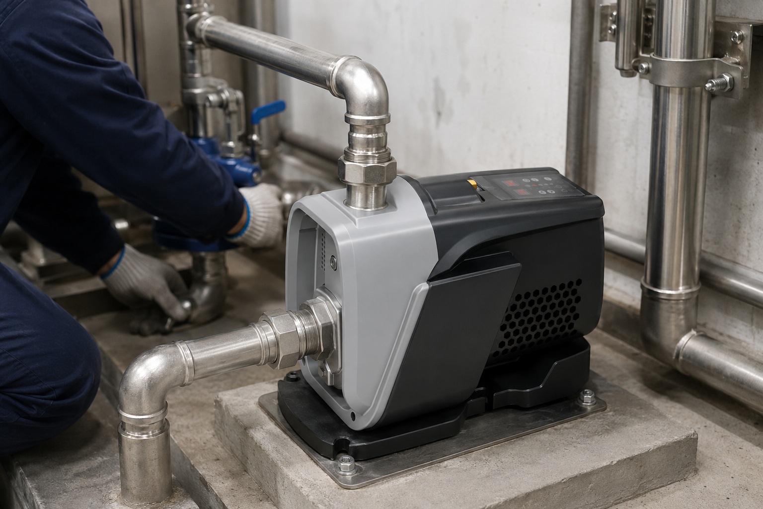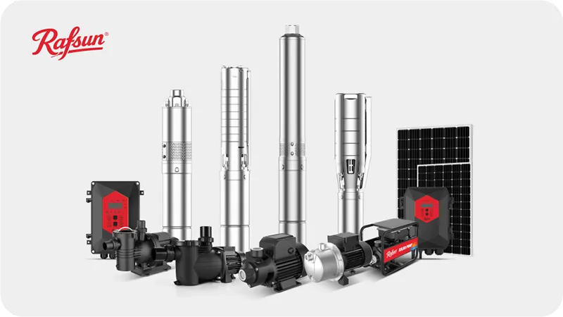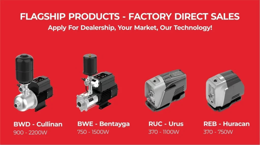
Struggling to grasp how complex pump systems operate?
This knowledge gap can lead to poor system selection and costly operational errors.
Understanding the fundamentals is the first step toward efficiency.
A pump system works by converting mechanical energy into hydraulic energy.
It uses a motor to drive a pump, which creates a pressure differential.
This pressure moves a fluid, like water, from an inlet point, through a network of pipes, to a designated discharge point, overcoming system resistance.
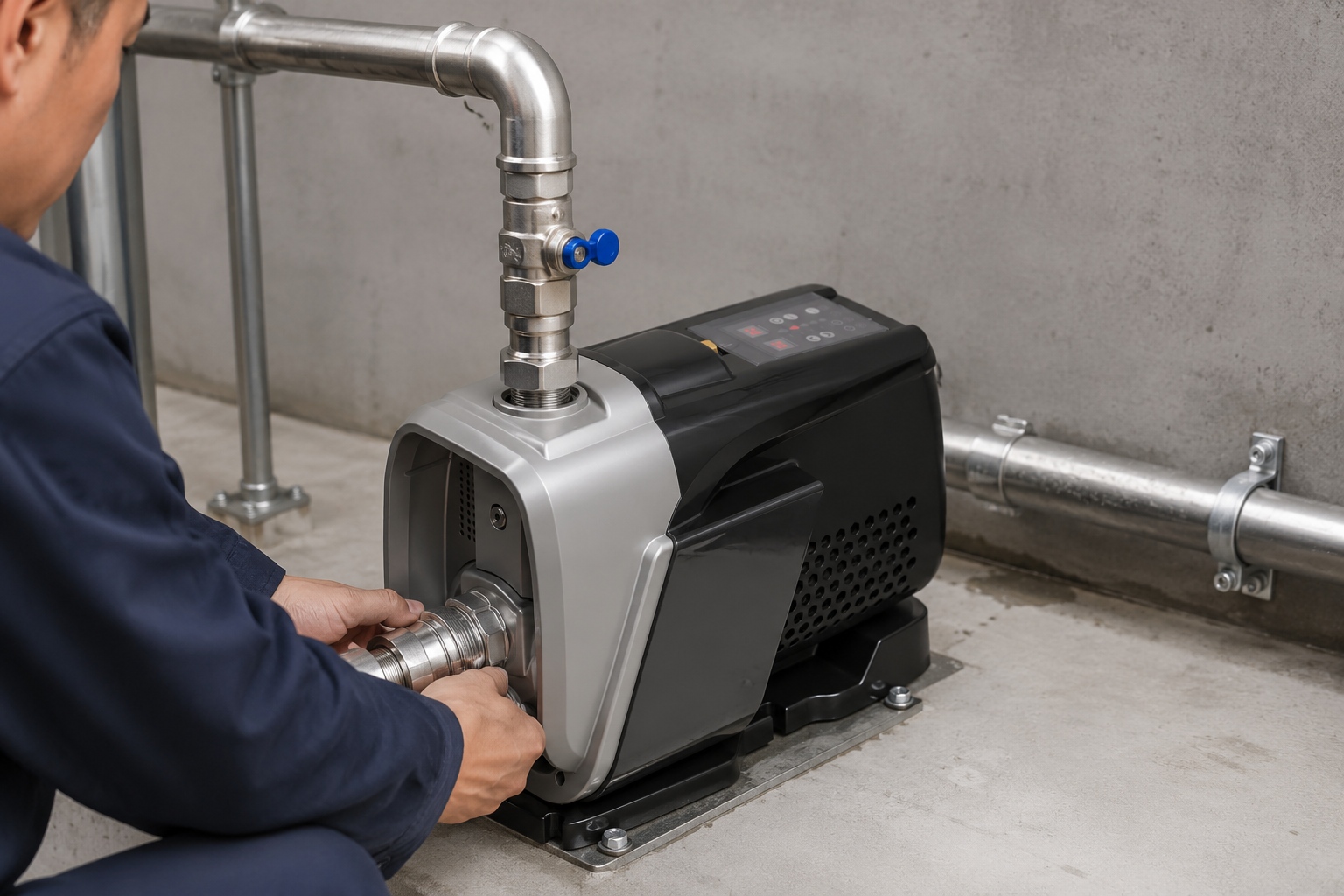
Now that we have a general picture, it's clear that a pump is more than just a single machine.
It's an integrated system where every component plays a crucial role.
Understanding how these parts interact is essential for anyone looking to procure, operate, or maintain these systems effectively.
Let's dive deeper into the specific elements and processes that make a pump system function, revealing how proper design and control unlock major gains in performance and longevity.
Breaking Down the Core Components of a Pump System
Confused by the various parts that make up a pumping assembly?
This can make troubleshooting and maintenance a daunting task.
Identifying each component and its function is crucial for effective system management.
A typical pump system consists of the pump unit (casing, impeller), the driver (motor), piping (suction and discharge lines), and control elements like valves and sensors.
These components coordinate to contain, move, and regulate the fluid from its source to the destination.
To truly understand how a pump system functions, we must first dissect its anatomy.
Each part is engineered for a specific purpose, and its design and material directly impact the system's overall performance, efficiency, and lifespan.
Approximately 90% of pump failures can be traced back to issues with system components rather than the pump itself, highlighting the importance of a holistic view.
The Pump Unit: The Heart of the System
The pump unit is where the energy conversion happens.
It is not a single piece but a collection of precision-engineered parts.
-
Casing (Volute): This is the outer shell that contains the fluid.
In centrifugal pumps, it's designed to slow down the fluid from the impeller, converting velocity into pressure.
-
Impeller: This rotating component has vanes that transfer energy from the motor to the fluid, accelerating it outward.
The design of the impeller (open, semi-open, or closed) dictates the pump's suitability for different fluids, from clean water to slurries with solids.
-
Shaft: This rod connects the impeller to the motor, transmitting the rotational force.
It must be perfectly straight and robust to handle torque and prevent vibration.
-
Seals: Mechanical seals or packing are used to prevent fluid from leaking out along the shaft.
Seal failure is a common maintenance issue, accounting for a significant portion of pump downtime.
The Support Structure and Ancillaries
Beyond the core pump, other components are vital for stability and control.
-
Bearings: These support the shaft, reducing friction and allowing for smooth rotation.
Proper lubrication and maintenance of bearings can extend a pump's operational life by over 50%.
-
Piping Network: This includes the suction pipe, which brings fluid to the pump, and the discharge pipe, which carries it away.
The diameter, material, and layout of piping are critical as they determine the system's friction losses.
-
Valves: These are used to control the system.
Isolation valves allow the pump to be taken offline for maintenance, check valves prevent backflow, and control valves regulate the flow rate or pressure.
The table below summarizes the primary function of each key component.
| Component | Primary Function | Key Consideration |
|---|---|---|
| Casing | Contains the fluid and converts velocity to pressure. | Material compatibility with the fluid, pressure rating. |
| Impeller | Transfers energy to the fluid, creating flow. | Design (open/closed), diameter, material for abrasion resistance. |
| Shaft | Transmits torque from the motor to the impeller. | Straightness, strength to avoid deflection. |
| Seals | Prevent leakage along the shaft. | Type (mechanical/packing), material compatibility. |
| Piping | Conveys the fluid to and from the pump. | Diameter and layout to minimize friction loss. |
| Valves | Control flow, pressure, and direction. | Type (check, gate, globe), actuation method. |
Understanding these individual parts is the first step.
Next, we will explore how they work in unison to move fluid through the system.
The Pumping Cycle: How Fluid is Actually Moved
Ever wonder about the exact process that moves water from point A to B?
Ignoring this can lead to inefficient operation and energy waste.
Knowing the cycle helps optimize both performance and cost.
The pumping cycle begins by creating a low-pressure zone at the pump's inlet, drawing fluid in.
The pump's mechanism, like a rotating impeller, then energizes the fluid, increasing its velocity and pressure.
This high-pressure fluid is then forced out the discharge port and through the piping system.
The movement of fluid in a pump system is a continuous, dynamic process governed by fundamental principles of fluid dynamics.
It is not simply about suction and discharge; it is about precise pressure management.
The process varies significantly between the two main categories of pumps: centrifugal and positive displacement.
Understanding these differences is key to selecting the right technology for an application, as a mismatch can reduce efficiency by as much as 20-30%.
The Centrifugal Pump Cycle
Centrifugal pumps are the most common type, used in over 75% of industrial applications.
Their operation is based on imparting velocity to a fluid.
-
Induction: As the motor spins the impeller, fluid is drawn into the center, or "eye," of the impeller due to the low pressure created by the rotating vanes.
-
Acceleration: The spinning impeller vanes catch the fluid and accelerate it radially outward at high speed.
This acceleration is a direct conversion of mechanical energy into kinetic energy.
-
Discharge: The high-velocity fluid exits the impeller and enters the pump casing (volute).
The volute's progressively wider shape forces the fluid to slow down.
According to Bernoulli's principle, this decrease in kinetic energy is converted into high potential energy, or pressure.
This pressure is what drives the fluid through the system.
The Positive Displacement (PD) Pump Cycle
Positive displacement pumps work differently.
They do not create velocity but instead trap a fixed volume of fluid and force it out.
-
Trapping: An expanding cavity is created on the suction side, drawing in and trapping a set volume of fluid.
This mechanism can be a reciprocating piston, a rotating gear, or a flexible diaphragm.
-
Displacement: The cavity's volume is then reduced, physically squeezing and displacing the trapped fluid.
This action increases the fluid's pressure directly.
-
Expulsion: The high-pressure fluid is forced out the discharge port.
Unlike a centrifugal pump, a PD pump will produce flow against almost any pressure, which is why a pressure relief valve is a mandatory safety feature.
The table below contrasts the two primary pumping cycles.
| Feature | Centrifugal Pump Cycle | Positive Displacement Pump Cycle |
|---|---|---|
| Principle | Converts velocity to pressure (kinetic). | Traps and displaces a fixed volume (static). |
| Flow Rate | Varies with system pressure (head). | Relatively constant, regardless of pressure. |
| Pressure | Generated by fluid velocity and casing design. | Generated by physically squeezing the fluid. |
| Suitability | High-flow, low-viscosity fluids (e.g., water). | High-pressure, high-viscosity fluids (e.g., oils, slurries). |
This cyclic action, whether centrifugal or positive displacement, is what ultimately defines a pump's performance characteristics and its suitability for a specific task.
A Look at Different Pump Types and Their Applications
Choosing the wrong pump type can severely compromise your system's efficiency.
This mistake leads to higher energy bills and frequent maintenance.
Matching the pump type to the job is essential for reliable operation.
Pumps are broadly classified into centrifugal and positive displacement types.
Centrifugal pumps use a rotating impeller for high-flow applications with low-viscosity fluids like water.
Positive displacement pumps trap and move fluid, ideal for high-pressure or viscous liquid applications.
The world of pumps is vast, but nearly all designs fall under two main families: Dynamic (Centrifugal) and Positive Displacement.
The choice between them is the most fundamental decision in pump system design.
It is dictated by the required flow rate, pressure, and the properties of the fluid being handled.
Selecting a centrifugal pump for a high-viscosity application, for instance, could lead to a performance drop of over 40% and rapid component wear.
Let's break down the major categories and their common uses.
Dynamic Pumps: The Centrifugal Family
This family uses a spinning impeller to add energy to the fluid.
They are defined by variable flow that changes with system pressure.
-
End-Suction Pumps: The most common configuration, where the suction nozzle is on the opposite side of the casing from the shaft.
They are workhorses for water supply, HVAC, and general industrial services.
-
Submersible Pumps: The entire assembly, including the motor, is hermetically sealed and submerged in the fluid.
This design is ideal for deep well water extraction, wastewater management, and drainage, as it prevents pump cavitation and requires no priming.
-
Vertical Multistage Pumps: These pumps have multiple impellers stacked vertically on a single shaft.
Each stage adds more pressure, making them perfect for high-pressure applications with a small footprint, such as reverse osmosis systems and boiler feeds.
Positive Displacement Pumps: The Specialists
This family moves fluid by trapping a fixed amount and forcing (displacing) it.
They deliver a constant flow regardless of system pressure.
-
Reciprocating Pumps: These use a piston, plunger, or diaphragm that moves back and forth to displace fluid.
They excel in high-pressure applications like chemical injection and high-pressure cleaning, generating pressures well over 1,000 bar.
-
Rotary Pumps: These use rotating elements like gears, lobes, or screws to move fluid.
They are the go-to solution for viscous fluids such as oils, polymers, and food products because their gentle handling action minimizes shearing of the fluid.
The following table provides a quick reference for selecting a pump type based on application needs.
| Pump Type | Typical Flow Rate | Typical Pressure | Common Fluids | Key Advantage |
|---|---|---|---|---|
| Centrifugal | High | Low to Medium | Water, light chemicals | High efficiency at best efficiency point (BEP). |
| Submersible | Medium to High | Varies (by depth) | Water, wastewater | Self-priming, no cavitation risk. |
| Multistage | Low to Medium | Very High | Clean water | Achieves high pressure efficiently. |
| Reciprocating | Low | Extremely High | Chemicals, slurry | Generates very high pressures. |
| Rotary (Gear/Lobe) | Low to Medium | Medium | Viscous oils, foods | Handles high viscosity and is self-priming. |
The right choice ensures your system operates not just effectively, but also economically, for years to come.
The Role of Motors and Drives in Pump Efficiency
Think a pump's performance is all about its hydraulics?
Overlooking the motor and drive can lead to massive energy waste.
In fact, energy costs can account for up to 85% of a pump system's total life cycle cost.
Optimizing the motor and drive is a direct path to savings.
The motor converts electrical energy into the mechanical motion that turns the pump's shaft.
Variable frequency drives (VFDs) control the motor's speed, allowing the pump's output to be precisely matched to system demand, which dramatically reduces energy consumption compared to running at a fixed speed.
The motor and its control system are the engine of the pump system.
While the pump's hydraulic design sets its potential efficiency, it's the motor and drive that determine how much of that potential is realized in practice.
A standard induction motor running at full speed wastes significant energy when system demand is low.
Implementing a VFD can reduce a pump's energy use by 30-50% by simply slowing it down, following the principle that power consumption is proportional to the cube of the speed.
Electric Motors: The Power Source
The vast majority of pumps are driven by AC induction motors.
Their selection is critical for reliability and efficiency.
-
Efficiency Class: Motors are rated for efficiency (e.g., IE3 Premium Efficiency, IE4 Super Premium).
Upgrading from an older, less efficient motor to an IE3 or IE4 class motor can yield energy savings of 2-5%, which adds up significantly over the motor's lifetime.
-
Sizing: Correctly sizing the motor is crucial.
An oversized motor operates in a less efficient part of its performance curve and has a lower power factor, leading to wasted energy.
A motor should be sized to operate at 75-95% of its rated load for optimal efficiency.
-
Enclosure Type: The motor's enclosure (e.g., TEFC - Totally Enclosed Fan Cooled) protects its internal components from the operating environment (dust, moisture), which is vital for longevity.
Variable Frequency Drives (VFDs): The Efficiency Brains
A VFD is a power controller that adjusts the frequency and voltage supplied to an electric motor.
This enables precise speed control.
-
Energy Savings: The core benefit of a VFD is energy reduction.
According to the Affinity Laws for pumps, a 20% reduction in pump speed can result in nearly 50% energy savings.
This is because flow is proportional to speed, pressure is proportional to the square of the speed, and power is proportional to the cube of the speed.
-
Process Control: VFDs allow for tight control over flow and pressure without using inefficient throttling valves.
This leads to more stable system operation and higher product quality in many industrial processes.
-
Soft Starting: VFDs provide a 'soft start' by gradually ramping up the motor speed.
This reduces the huge inrush current of a direct-on-line start (which can be 6-8 times the normal running current) and minimizes mechanical stress on the entire system, extending the life of pipes, valves, and the pump itself.
This table highlights the impact of VFDs on pump operation.
| Parameter | Fixed Speed (with Throttling Valve) | Variable Speed (with VFD) |
|---|---|---|
| Motor Speed | Constant (100%) | Variable (e.g., 50-100%) |
| Energy Use | High, as excess energy is lost across the valve. | Proportional to system demand; very low at low flow. |
| System Stress | High mechanical and electrical stress on startup. | Low, due to soft-start capability. |
| Control Precision | Limited and inefficient. | High, with fast response to demand changes. |
In modern pump systems, the combination of a high-efficiency motor and a VFD is no longer a luxury but a standard for achieving cost-effective and reliable operation.
Understanding Pump Curves and System Curves
Buying a pump without analyzing its curve is a gamble.
This guesswork often results in a pump that is oversized or undersized for the job.
It leads to inefficiency, high energy costs, and premature failure.
A pump curve is a graph showing the pump's performance, specifically the relationship between flow rate (horizontal axis) and pressure, or head (vertical axis).
A system curve shows the head required to move fluid through a specific piping system at various flow rates.
The point where these two curves intersect is the operating point.
The performance curve is the pump's DNA.
It provides a complete picture of how a pump will behave under different conditions.
System designers and operators must know how to read these curves to ensure a pump operates at or near its Best Efficiency Point (BEP).
The BEP is the point on the curve where the pump is most efficient at converting energy into fluid movement.
Operating a pump away from its BEP, even by just 15%, can increase energy consumption by 10% and significantly elevate vibration and radial forces, leading to accelerated wear on seals and bearings.
Reading a Pump Performance Curve
A standard pump curve chart contains a wealth of information.
-
Head vs. Flow (H-Q) Curve: This is the main curve, showing the head (pressure) the pump can generate at a given flow rate.
Generally, as the flow rate increases, the head decreases.
-
Best Efficiency Point (BEP): This is marked on the H-Q curve and represents the most efficient operating condition for the pump.
Efficiency contour lines often surround the BEP, showing how efficiency drops as you move away from it.
-
Power Curve: This curve shows the brake horsepower (BHP) required by the pump at different flow rates.
It typically rises with the flow rate.
-
NPSHr Curve: The Net Positive Suction Head Required (NPSHr) curve shows the minimum pressure required at the pump's suction port to prevent cavitation.
This value increases with flow rate.
Developing the System Curve
The system curve is unique to each piping installation.
It represents the total resistance the pump must overcome.
-
Static Head: This is the vertical height difference between the source fluid level and the discharge point.
It is constant regardless of flow rate and forms the starting point of the system curve on the vertical axis.
-
Friction Head: This is the energy lost due to friction as the fluid moves through pipes, fittings, and valves.
Friction head is not constant; it increases exponentially as the flow rate increases.
It can be calculated using formulas like the Darcy-Weisbach or Hazen-Williams equations.
The system curve is plotted by adding the static head and friction head at various flow rates.
| Flow Rate (GPM) | Static Head (ft) | Friction Head (ft) | Total Head (ft) - System Curve |
|---|---|---|---|
| 0 | 50 | 0 | 50 |
| 50 | 50 | 5 | 55 |
| 100 | 50 | 20 | 70 |
| 150 | 50 | 45 | 95 |
The Operating Point: Where Pump Meets System
The operating point is where the pump's H-Q curve intersects the system curve.
This is the actual head and flow rate the pump will deliver in that specific system.
The goal is to select a pump where this operating point falls as close as possible to the pump's BEP.
If the operating point is far to the left of the BEP, the pump will experience high pressure, low flow, and internal recirculation.
If it is far to the right, the pump will be at risk of cavitation and motor overload.
Mastering the interplay between pump and system curves is the key to designing an efficient, reliable, and long-lasting pumping system.
Conclusion
A pump system is a dynamic interplay of components.
Understanding its core mechanics, types, and controls is essential for optimizing performance and achieving significant long-term energy and cost savings.
FAQs
What is the primary function of a pump?
A pump's main job is to move fluids (liquids or gases) by converting mechanical energy into hydraulic energy, creating flow and pressure within a system.
What is the difference between a pump and a motor?
A motor converts electrical energy into mechanical rotation.
A pump uses that mechanical rotation to move fluid.
The motor powers the pump.
What is pump head vs pressure?
Head is the height a pump can lift a fluid, measured in feet or meters.
Pressure is the force exerted by the fluid, measured in psi or bar.
Head is independent of fluid density.
What happens if a pump runs dry?
Running a pump dry causes rapid overheating due to lack of fluid for cooling and lubrication.
This can destroy seals, bearings, and impellers within minutes.
What is pump cavitation and why is it bad?
Cavitation is the formation and collapse of vapor bubbles inside a pump.
This collapse creates intense shockwaves that erode internal components, causing severe damage, noise, and vibration.
What is a pump's best efficiency point (BEP)?
The Best Efficiency Point (BEP) is the flow rate at which a pump operates most efficiently, converting the highest percentage of input power into fluid movement.
How does a variable frequency drive (VFD) save energy on a pump?
A VFD saves energy by slowing down the pump's motor to precisely match the system's demand, since power use is proportional to the cube of the speed.
What is NPSH in a pump?
NPSH (Net Positive Suction Head) is the pressure at the pump's suction needed to prevent cavitation.
The available NPSH from the system must exceed the required NPSH of the pump.