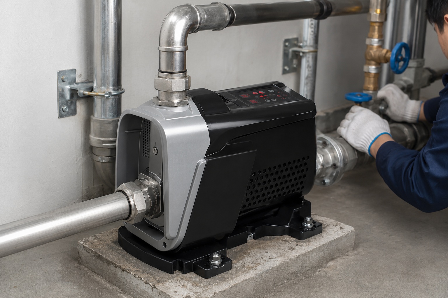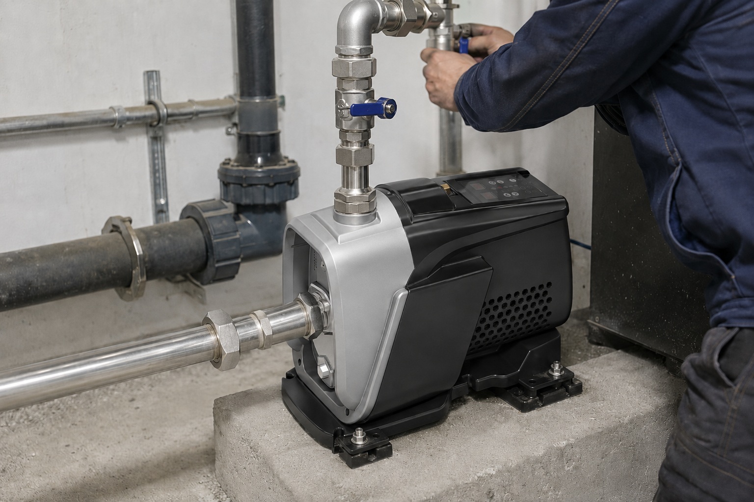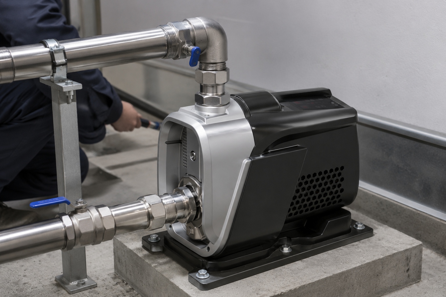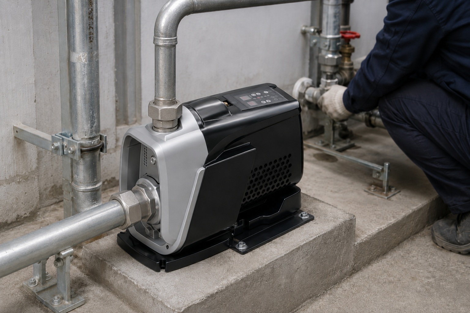
Struggling to achieve the high pressure your system demands?
A single impeller pump might not be providing the necessary force, leading to inefficient operations and system failures.
A multistage centrifugal pump has two or more impellers. The exact number can range from two up to sixteen, or even more for highly specialized applications. Each impeller, or stage, incrementally boosts the fluid's pressure to achieve very high discharge heads.
You now know that "multistage" means more than one impeller.
But this simple answer opens a gateway to more critical questions for your business.
How does the number of impellers directly impact performance, efficiency, and cost?
Understanding the mechanics behind these stages is key to selecting the right pump that not only meets your pressure requirements but also offers the best long-term value.
Let's explore the details that separate a standard choice from a strategic investment.
What is a Multistage Centrifugal Pump?
Wondering why some applications need more than a standard pump?
Standard pumps often fail to deliver the high pressure required for industrial processes or moving water over long distances, causing system bottlenecks.
A multistage centrifugal pump is a type of pump that uses two or more impellers to increase fluid pressure. The fluid passes sequentially through each impeller, with every stage adding more pressure, allowing the pump to achieve much higher heads than a single-stage pump.
A multistage pump works on a simple yet powerful principle.
It is essentially a series of individual pumps connected within a single housing.
The process begins when fluid enters the pump at the suction inlet.
It flows into the first chamber, where the first spinning impeller imparts velocity to the fluid.
This high-velocity fluid then moves into a diffuser.
The diffuser is a stationary component with expanding passages.
It slows down the fluid.
This action converts the kinetic energy (velocity) into potential energy (pressure).
The now-pressurized fluid from the first stage is then expertly guided into the eye of the second impeller.
This process repeats itself through each subsequent stage.
Each impeller and diffuser pair acts as a pressure-boosting module.
This sequential pressurization is the core advantage of a multistage pump.
It allows for a significant and controlled increase in the final discharge pressure.
Classification of Multistage Pumps
Multistage pumps are not all the same.
They can be categorized based on their shaft orientation, which significantly impacts their footprint, installation, and maintenance.
The two primary types are vertical and horizontal multistage pumps.
- Vertical Multistage Pumps: In these pumps, the shaft is oriented vertically. They typically have a smaller footprint, making them ideal for installations where floor space is limited. Their design can simplify piping connections in certain layouts.
- Horizontal Multistage Pumps: These pumps have a horizontally oriented shaft. They are often preferred for their ease of access for maintenance and inspection, as the internal components can be reached without disturbing the motor or piping.
Understanding these classifications is the first step in matching pump design to your specific operational environment.
Pressure and Flow Dynamics
The performance of a multistage pump is defined by its ability to generate pressure (head) and move a certain volume of fluid (flow).
The number of stages directly correlates with the total pressure output.
Adding more stages increases the total head the pump can generate.
However, the flow rate remains relatively constant and is determined by the size and design of the first impeller.
Think of it as a team effort.
Each impeller adds its push, but they are all pushing the same stream of water.
This relationship is crucial for pump selection.
| Number of Stages | Total Head (Pressure) | Flow Rate | Typical Use Case |
|---|---|---|---|
| 2-4 | Moderate-High | Constant | Small-scale boiler feed, reverse osmosis |
| 5-8 | High | Constant | Industrial cleaning, water supply for tall buildings |
| 9+ | Very High | Constant | Long-distance water transfer, mine dewatering |
As you can see, the choice is not just about needing "high pressure." It is about a calculated decision based on the precise head required for your system to operate efficiently.
A pump with a 15% higher pressure capability than needed can lead to increased energy consumption and component wear over its lifespan.
The Science Behind Impellers
Confused about how a simple spinning disc can move massive amounts of water?
Without understanding the impeller's function, it's impossible to grasp how a pump generates pressure, leading to poor purchasing and operational decisions.
An impeller is the rotating heart of a centrifugal pump. It features a series of curved vanes that spin to accelerate fluid outwards from the center. This acceleration creates a pressure differential, drawing more fluid in and pushing it out with increased energy.
An impeller is the critical component that transfers energy from the motor to the fluid.
Its design is a masterclass in fluid dynamics.
As the motor turns the pump shaft, the impeller spins rapidly.
This rotation creates a strong centrifugal force.
Fluid is drawn into the center of the impeller, known as the impeller eye.
The spinning vanes then catch this fluid.
They accelerate it radially outward at high speed.
This action is similar to a spinning merry-go-round pushing you to the edge.
As the fluid is flung outward, two things happen simultaneously.
First, its velocity increases dramatically.
Second, a low-pressure area is created at the impeller eye, which continuously pulls more fluid into the pump.
This creates the suction effect.
The high-velocity fluid exits the impeller and enters the pump casing (volute) or a diffuser.
Here, the fluid's speed is intentionally reduced.
According to Bernoulli's principle, as the fluid's velocity decreases, its pressure must increase.
The pump's casing is specially shaped to manage this energy conversion efficiently, transforming the velocity head into a higher pressure head.
In a multistage pump, this pressurized fluid doesn’t exit the pump.
Instead, it is directed into the eye of the next impeller in the series, where the process is repeated, adding more pressure with each stage.
Key Impeller Characteristics
The performance of an impeller is not accidental.
It is determined by several specific design factors.
Understanding these can help you evaluate a pump's suitability beyond its basic specifications.
- Impeller Diameter: A larger diameter generally means the impeller can move fluid at a higher velocity, resulting in a higher head and flow rate. This is one of the primary factors adjusted by designers to create a family of pumps.
- Vane Shape and Number: The curvature, thickness, and number of vanes are meticulously engineered. Vane design influences efficiency, the pump's ability to handle solids, and its Net Positive Suction Head Required (NPSHr). Fewer, wider vanes might be used for pumps handling slurry, while more, thinner vanes are common in clear water applications to maximize efficiency, which can be as high as 90% in well-designed pumps.
- Impeller Type (Open, Semi-Open, Closed): This is a critical distinction.
Comparing Impeller Types
The choice between open, semi-open, and closed impellers depends entirely on the fluid being pumped.
Using the wrong type can lead to rapid clogging, wear, or inefficiency.
| Impeller Type | Structure | Efficiency | Solids Handling | Common Applications |
|---|---|---|---|---|
| Closed | Vanes are enclosed between two shrouds (discs). | High (up to 90%) | Poor | Clean liquids like water. This is the most common type in multistage pumps for boiler feed, pressure boosting, and reverse osmosis. |
| Semi-Open | Vanes are attached to a back shroud, but open on the front side. | Medium | Fair | Liquids with some small solids or fibrous materials. Used in some process industries and wastewater applications. |
| Open | Vanes are attached to a central hub, with no shrouds. | Lower | Excellent | Slurries, liquids with high solids content, and for easier cleaning. Common in food processing and pulp and paper industries. |
For most multistage centrifugal pump applications focused on high-pressure clean water, the closed impeller is the standard.
Its design minimizes fluid recirculation and maximizes the conversion of velocity to pressure.
This results in the higher efficiencies that are critical for energy-intensive, continuous-duty operations.
Determining the Right Number of Impellers
Do you risk over-specifying a pump and wasting capital, or under-specifying and facing system failure?
Choosing the wrong number of stages means paying for unused capacity or, worse, not meeting the required pressure, leading to operational shutdown.
The correct number of impellers is determined by the required Total Dynamic Head (TDH) of your system. You calculate the pressure needed, convert it to head, and select a multistage pump where the head-per-stage performance curve meets the total requirement with the fewest stages.
Selecting the right number of impellers is a technical process, not a guess.
It is about precisely matching the pump's capability to your system's demands.
The first step is to calculate the Total Dynamic Head (TDH).
TDH is the total equivalent height that a fluid is to be pumped, considering all losses.
It is the sum of several factors.
This includes the static head, which is the vertical distance you are lifting the fluid.
It also includes the friction head, which accounts for pressure losses due to friction in pipes and fittings.
Finally, it considers the pressure head, which is the pressure required at the final discharge point.
Once you have the TDH value, you consult a pump manufacturer's performance curve.
These curves are essential engineering tools.
They graphically show a pump's performance.
Specifically, they chart the head (pressure) a pump can generate at various flow rates.
For a multistage pump, you will often find curves for a single stage or for the entire pump series (e.g., 2-stage, 3-stage, 4-stage models).
The goal is to find the pump that provides your required TDH and flow rate at its Best Efficiency Point (BEP).
Operating a pump at its BEP ensures the lowest energy consumption and longest possible service life.
It's the sweet spot of pump performance.
A Practical Calculation Example
Let's walk through a simplified example to make this concept concrete.
Imagine you need to select a pump for a reverse osmosis (RO) system.
Your calculations show the following requirements:
- Required Flow Rate: 50 cubic meters per hour (m³/h)
- Required Discharge Pressure: 15 bar
First, you must convert the required pressure into head.
The conversion is approximately 1 bar = 10.2 meters of head for water.
*Required Head (TDH) = 15 bar 10.2 m/bar = 153 meters**
Now, you look at the performance data for a family of multistage pumps.
Let's say you are considering a pump series where each stage provides a certain amount of head.
Matching System Requirements to Pump Curves
You find a manufacturer's datasheet for a suitable pump model.
The curve for a single stage of this model shows that at your required flow rate of 50 m³/h, one stage can generate 28 meters of head.
Now, the calculation is straightforward.
Number of Stages Needed = Total Required Head / Head per Stage
Number of Stages Needed = 153 m / 28 m/stage ≈ 5.46 stages
You cannot have a fraction of a stage.
Therefore, you must round up to the next whole number.
You would need a 6-stage pump.
A 5-stage pump would generate only 5 * 28 = 140 meters of head, which is insufficient.
A 6-stage pump will generate 6 * 28 = 168 meters of head.
This provides a comfortable safety margin of about 10% (168m vs. 153m), which is good practice to account for future system degradation or minor miscalculations.
Here is how the selection process breaks down:
| Step | Action | Data Required | Outcome |
|---|---|---|---|
| 1 | Define System Requirements | Flow Rate & Discharge Pressure | Target flow and pressure values |
| 2 | Calculate Total Dynamic Head (TDH) | Discharge Pressure, Static Lift, Friction Loss | A single "Head" value in meters or feet |
| 3 | Consult Pump Performance Curves | Manufacturer's datasheets | Find a pump model that operates at your flow rate |
| 4 | Determine Head per Stage | Read the head value at your flow rate on the single-stage curve | A "Head per Stage" value |
| 5 | Calculate Number of Stages | TDH / Head per Stage | The theoretical number of stages |
| 6 | Select the Pump | Round up to the nearest whole number of stages | The final pump model (e.g., "Model XYZ-6") |
Choosing a pump with too many stages is a common mistake.
This leads to an oversized pump that operates far from its BEP, wasting significant amounts of energy and money over its lifetime.
Properly sizing the pump is one of the most impactful decisions in system design.
Applications and Industry Impact
Are you unsure if a multistage pump is the right solution for your specific industry need?
Misapplying a pump can lead to inefficiency, premature wear, and costly downtime, impacting your entire operation's productivity and profitability.
Multistage pumps are essential in applications requiring high-pressure fluid transfer. They are widely used in boiler feed water systems, reverse osmosis and desalination, high-pressure cleaning, mine dewatering, and boosting water pressure in tall buildings and municipal water networks.
The unique ability of multistage pumps to generate high pressure efficiently makes them invaluable across a wide spectrum of industries.
They are not a one-size-fits-all solution.
They are a specialized tool for demanding jobs.
Where a single-stage pump provides volume, a multistage pump provides force.
This distinction is crucial.
In many industrial processes, achieving and maintaining a specific high pressure is a non-negotiable requirement for the process to work at all.
For example, in reverse osmosis, pressures exceeding 60-70 bar are needed to overcome the natural osmotic pressure of saltwater and produce fresh water.
Only a multistage pump can achieve this pressure efficiently and reliably on a large scale.
Similarly, power plants rely on multistage pumps to feed water into boilers.
The pressure required must be significantly higher than the steam pressure inside the boiler, a task perfectly suited for these pumps.
The failure of a boiler feed pump can take an entire power station offline.
This highlights the critical role these machines play.
Deep Dive into Key Applications
Let's examine how the features of multistage pumps are leveraged in specific sectors.
The design and material selection for a pump in a desalination plant will be very different from one used for mine dewatering.
- Boiler Feed Water: This is a classic application. Water must be injected into a high-pressure steam boiler. The pumps must handle high temperatures and high pressures simultaneously. Materials like stainless steel or even duplex stainless steel are often required to prevent corrosion and withstand the demanding conditions. Reliability is paramount, as pump failure means a loss of power generation.
- Reverse Osmosis (RO) and Desalination: These processes require extremely high pressures to force water through semi-permeable membranes. Vertical multistage pumps are often used in smaller commercial RO systems, while large, horizontal split-case multistage pumps are the workhorses of municipal-scale desalination plants. Corrosion resistance is critical, so materials like Duplex 2205 or Super Duplex 2507 are used, which can increase the pump cost by 30-50% but are necessary for a long service life.
- High-Pressure Cleaning: In industries from food processing to heavy equipment manufacturing, high-pressure water jets are used for cleaning and surface preparation. Multistage pumps provide the consistent, high-pressure stream of water needed to power these systems effectively.
- Mine Dewatering: Mines often extend deep below the water table. Multistage pumps are used to lift water from the bottom of the mine to the surface. These are often large, robustly built pumps that need to handle abrasive particles and run continuously for long periods. They must overcome immense static head—the vertical distance back to the surface.
Matching Pump Type to Application
The choice between a vertical or horizontal multistage pump is also heavily influenced by the application.
This table illustrates some common pairings.
| Application | Predominant Pump Type | Rationale for Choice |
|---|---|---|
| Commercial Building Boosters | Vertical Multistage | Small footprint saves valuable mechanical room space. Inline piping connections simplify installation. Typically handle clean, potable water. |
| Industrial Boiler Feed | Horizontal Multistage (Ring Section or Split Case) | Ease of maintenance. The "between bearings" design of split case pumps provides high rotor stability for high-energy applications. Critical for reliability in power generation. |
| Large-Scale Desalination | Horizontal Multistage (Split Case) | High flow rates and extremely high pressures. The robust design and ease of service for internal components are essential for these massive, critical infrastructure projects. |
| Mine Dewatering | Vertical Turbine or Horizontal Multistage | Vertical turbine pumps can be submerged deep in the mine shaft. Horizontal pumps are used in underground pumping stations. Both are selected for robustness and ability to handle abrasive wear. |
Ultimately, the impact of multistage pumps is seen in the enabling of modern technology.
Without them, producing clean water at scale, generating electricity efficiently, and constructing skyscrapers would be significantly more challenging and costly.
They are a foundational component of modern industrial infrastructure.
Conclusion
A multistage pump has two or more impellers.
The exact number depends on the pressure your system requires, making proper calculation the key to an efficient and cost-effective operation.
Frequently Asked Questions
Can a pump have 2 impellers?
Yes, a pump with two impellers is the most basic form of a multistage pump. It's called a two-stage pump and is used when pressure needs are slightly higher than a single-stage pump can provide.
What is the difference between single-stage and multistage pumps?
A single-stage pump has one impeller and is ideal for low-head, high-flow applications. A multistage pump uses two or more impellers sequentially to achieve high-head, lower-flow outputs.
How does a multistage pump increase pressure?
Each impeller and diffuser set, or "stage," adds a set amount of pressure to the fluid. The fluid moves from one stage to the next, with its pressure increasing sequentially until it exits the pump.
What are the two types of multistage pumps?
The two main types are vertical and horizontal multistage pumps. The classification is based on the orientation of the pump shaft, which affects installation footprint and maintenance access.
How do you identify a multistage pump?
A multistage pump is often identifiable by its long, segmented casing. Each segment typically houses one impeller and diffuser assembly, making the casing visibly longer than that of a single-stage pump.
What is a 4 stage pump?
A 4-stage pump is a multistage centrifugal pump that contains four impellers arranged in series. It is used to generate a pressure approximately four times higher than a single, identical impeller could produce.